1VD-FTV EMISSION CONTROL EGR VALVE INSTALLATION
CAUTION / NOTICE / HINT
- NOTICE:
- ·
When replacing the injectors (including shuffling the injectors between the cylinders), common rail, cylinder head, or intake manifold, it is necessary to replace the injection pipes with new ones.
·w/ DPF:
When fuel lines are disconnected, air may enter the fuel lines, leading to engine starting trouble. Therefore, perform forced regeneration and bleed the air from the fuel lines (See page Engine / Hybrid System>1VD-FTV (EMISSION CONTROL)>EMISSION CONTROL SYSTEM>ON-VEHICLE INSPECTION).
PROCEDURE

 25685
1.INSTALL EGR COOLER GASKET
Install a new gasket.
25630
2.INSTALL NO. 2 EGR VALVE ASSEMBLY
25620
3.INSTALL NO. 1 EGR VALVE ASSEMBLY
16297B
4.INSTALL NO. 9 WATER BY-PASS HOSE AND WATER HOSE
Connect the 2 water hoses.
Install the No. 9 water by-pass hose.
25613
5.INSTALL NO. 3 EGR PIPE
w/ DPF:
Install a new O-ring to the No. 3 water by-pass pipe.
Install 2 new gaskets.
Install the No. 3 EGR pipe with the 4 nuts and 4 bolts.
- Torque:
- 21 N*m (214 kgf*cm, 15 ft.*lbf)
6.INSTALL EGR VALVE ASSEMBLY WITH EGR COOLER
Install the EGR valve with EGR cooler with the 6 bolts.
- Torque:
- 21 N*m (214 kgf*cm, 15 ft.*lbf)
25602
7.INSTALL NO. 2 EGR PIPE SUB-ASSEMBLY
Install 2 new gaskets to the No. 2 EGR pipe.
Install the No. 2 EGR pipe with the 4 bolts.
- Torque:
- 29 N*m (296 kgf*cm, 21 ft.*lbf)
- NOTICE:
- ·
Press down the cooler side by hand while tightening the bolts on the cylinder head side.
·If the insulator installation stay is deformed, replace the No. 2 EGR pipe.
·If the clearance between the head and flange is 1 mm (0.0394 in.) or more, replace the No. 2 EGR pipe.
25601
8.INSTALL NO. 1 EGR PIPE SUB-ASSEMBLY
Install 2 new gaskets to the No. 1 EGR pipe.
Install the No. 1 EGR pipe with the 4 bolts.
- Torque:
- 29 N*m (296 kgf*cm, 21 ft.*lbf)
- NOTICE:
- ·
Press down the cooler side by hand while tightening the bolts on the cylinder head side.
·If the insulator installation stay is deformed, replace the No. 1 EGR pipe.
·If the clearance between the head and flange is 1 mm (0.0394 in.) or more, replace the No. 1 EGR pipe.
16289
9.CONNECT NO. 5 WATER BY-PASS PIPE
Connect the 2 hoses and install the bolt to connect the No. 5 water by-pass pipe.
- Torque:
- 10 N*m (102 kgf*cm, 7 ft.*lbf)
25615A
10.INSTALL EGR PIPE INSULATOR
17853B
11.INSTALL INTAKE MANIFOLD INSULATOR
17114D
12.INSTALL NO. 3 INTAKE MANIFOLD
82122
13.CONNECT NO. 2 ENGINE WIRE
17113
14.INSTALL INTAKE PIPE
Install a new gasket.
Install the intake pipe with the 4 bolts and 2 nuts.
- Torque:
- 21 N*m (214 kgf*cm, 15 ft.*lbf)
25614
15.INSTALL NO. 4 EGR PIPE
Install 2 new gaskets to the No. 4 EGR pipe.
Install the No. 4 EGR pipe with the 4 bolts.
- Torque:
- 21 N*m (214 kgf*cm, 15 ft.*lbf)
17136
16.INSTALL NO. 2 INTAKE MANIFOLD INSULATOR
17135A
17.INSTALL NO. 1 INTAKE MANIFOLD INSULATOR
23763
18.INSTALL NO. 3 NOZZLE LEAKAGE PIPE (w/ DPF)
23810A
19.INSTALL COMMON RAIL ASSEMBLY RH
23702
20.INSTALL INJECTION PIPE RH
11224
21.INSTALL CYLINDER HEAD COVER SILENCER RH (w/ DPF)
23705
22.INSTALL NO. 5 INJECTION PIPE SUB-ASSEMBLY
23243C
23.CONNECT FUEL PUMP MOTOR WIRE
23801L
24.INSTALL FUEL FILTER TO INJECTION PUMP FUEL PIPE SUB-ASSEMBLY
23820A
25.INSTALL COMMON RAIL ASSEMBLY LH
23765
26.INSTALL NO. 5 NOZZLE LEAKAGE PIPE (w/ DPF)
23812D
27.INSTALL NO. 2 FUEL PIPE (w/ DPF)
27148B
28.CONNECT CONNECTING WIRE (w/ DPF)
23701
29.INSTALL INJECTION PIPE LH
23764A
30.INSTALL NO. 4 NOZZLE LEAKAGE PIPE (w/ DPF)
11225
31.INSTALL CYLINDER HEAD COVER SILENCER LH (w/ DPF)
25706
32.INSTALL NO. 1 VACUUM TRANSMITTING PIPE SUB-ASSEMBLY (w/ DPF)
25860
33.INSTALL NO. 1 VACUUM SWITCHING VALVE ASSEMBLY (w/ DPF)
23706
34.INSTALL NO. 6 INJECTION PIPE SUB-ASSEMBLY
23802E
35.INSTALL NO. 2 FUEL PIPE SUB-ASSEMBLY (w/o DPF)
36.CONNECT ENGINE WIRE
16288
37.INSTALL NO. 4 WATER BY-PASS PIPE
16268M
38.INSTALL NO. 3 WATER BY-PASS PIPE (w/o Viscous Heater)
23274D
39.CONNECT FUEL HOSE
17885
40.INSTALL NO. 1 AIR CLEANER PIPE SUB-ASSEMBLY
87208
41.INSTALL HEATER WATER PIPE SUB-ASSEMBLY (w/ Viscous Heater)
17806
42.INSTALL NO. 2 AIR CLEANER PIPE SUB-ASSEMBLY
17364
43.INSTALL NO. 4 AIR TUBE
17342D
44.INSTALL NO. 2 AIR HOSE
17363K
45.INSTALL NO. 3 AIR TUBE
17341F
46.INSTALL NO. 1 AIR HOSE
17861
47.INSTALL INTAKE AIR CONNECTOR
17881
48.TEMPORARILY INSTALL NO. 1 AIR CLEANER HOSE
17705
49.INSTALL AIR CLEANER CAP SUB-ASSEMBLY
26100G
50.INSTALL DIESEL THROTTLE BODY ASSEMBLY LH
17947B
51.INSTALL NO. 3 INTERCOOLER SUPPORT BRACKET
Install the No. 3 intercooler support bracket with the 2 bolts.
- Torque:
- 21 N*m (214 kgf*cm, 15 ft.*lbf)
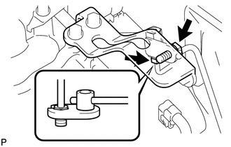
for Manual Transmission:
Connect the clutch tube to release cylinder 2 way with the bolt.
- Torque:
- 20 N*m (204 kgf*cm, 15 ft.*lbf)
Check that the union nut is tightened to the specified torque.
- Torque:
- 15 N*m (154 kgf*cm, 11 ft.*lbf)
- HINT:
-
Use the formula to calculate special torque values for situations where a union nut wrench is combined with a torque wrench (See page General>INTRODUCTION>REPAIR INSTRUCTION>PRECAUTION).
23265
52.INSTALL NO. 1 GAS FILTER
Install the No. 1 gas filter.
Connect the hose to the intake pipe.
31489
53.INSTALL TUBE CONNECTOR TO FLEXIBLE HOSE TUBE (for Manual Transmission)
17972
54.INSTALL AIR TUBE SUB-ASSEMBLY LH
31418
55.INSTALL CLUTCH HOSE (for Manual Transmission)
56.INSTALL DIESEL THROTTLE BODY ASSEMBLY RH
17971
57.INSTALL AIR TUBE SUB-ASSEMBLY RH
58.INSTALL NO. 2 ENGINE OIL LEVEL DIPSTICK GUIDE
87209
59.CONNECT WATER HOSE SUB-ASSEMBLY
17940D
60.INSTALL INTERCOOLER ASSEMBLY
61.CONNECT CABLE TO NEGATIVE BATTERY TERMINAL
- NOTICE:
-
When disconnecting the cable, some systems need to be initialized after the cable is reconnected (See page General>INTRODUCTION>REPAIR INSTRUCTION>INITIALIZATION).
Connect the cables to the negative (-) main battery and sub-battery terminals.
62.ADD ENGINE COOLANT
63.ADD CLUTCH FLUID
64.FILL BRAKE FLUID RESERVOIR (for Manual Transmission)
65.BLEED CLUTCH LINE (for Manual Transmission)
66.CHECK FLUID LEVEL IN RESERVOIR (for Manual Transmission)
67.INSPECT FOR CLUTCH FLUID LEAK (for Manual Transmission)
68.BLEED AIR FROM FUEL SYSTEM
69.INSPECT FOR FUEL LEAK
70.INSPECT FOR COOLANT LEAK
71.INSPECT FOR OIL LEAK
53292A
72.INSTALL UPPER RADIATOR SUPPORT SEAL
51405A
73.INSTALL NO. 1 ENGINE UNDER COVER SUB-ASSEMBLY
53806
74.INSTALL FRONT FENDER SPLASH SHIELD SUB-ASSEMBLY LH
53805
75.INSTALL FRONT FENDER SPLASH SHIELD SUB-ASSEMBLY RH
25620
76.PERFORM ELECTRIC EGR CONTROL VALVE COMPENSATION RESET