SUSPENSION CONTROL CONTROL VALVE ASSEMBLY REMOVAL
PROCEDURE

 1. SUSPENSION FLUID PRESSURE RELEASE
Lift up the vehicle so that the tires are lifted off the ground.
Connect the GTS to the DLC3 with the engine switch off.
Turn the engine switch on (IG).
Turn the GTS on.
Perform the front wheel vehicle height control reduction Active Test until the suspension fluid does not return to the reservoir tank.
Enter the following menus: Chassis / AHC / Active Test / Front Wheel Up/Down
Perform the rear wheel vehicle height control reduction Active Test until the suspension fluid does not return to the reservoir tank.
Enter the following menus: Chassis / AHC / Active Test / Rear Wheel Up/Down
Turn the GTS off.
Turn the engine switch off.
17430
2.REMOVE TAILPIPE ASSEMBLY
for 1GR-FE:
Remove the tailpipe (See page Engine / Hybrid System>1GR-FE (INTAKE / EXHAUST)>EXHAUST PIPE>REMOVAL).
for 1UR-FE:
Remove the tailpipe (See page Engine / Hybrid System>1UR-FE (INTAKE / EXHAUST)>EXHAUST PIPE>REMOVAL).
for 3UR-FE:
Remove the tailpipe (See page Engine / Hybrid System>3UR-FE (INTAKE / EXHAUST)>EXHAUST PIPE>REMOVAL).
for 1VD-FTV:
Remove the tailpipe (See page Engine / Hybrid System>1VD-FTV (INTAKE / EXHAUST)>EXHAUST PIPE(w/o DPF)>REMOVAL).
17420
3.REMOVE CENTER EXHAUST PIPE ASSEMBLY
for 1GR-FE:
Remove the center exhaust pipe for (See page Engine / Hybrid System>1GR-FE (INTAKE / EXHAUST)>EXHAUST PIPE>REMOVAL).
for 1UR-FE:
Remove the center exhaust pipe for (See page Engine / Hybrid System>1UR-FE (INTAKE / EXHAUST)>EXHAUST PIPE>REMOVAL).
for 3UR-FE:
Remove the center exhaust pipe for (See page Engine / Hybrid System>3UR-FE (INTAKE / EXHAUST)>EXHAUST PIPE>REMOVAL).
for 1VD-FTV:
Remove the center exhaust pipe for (See page Engine / Hybrid System>1VD-FTV (INTAKE / EXHAUST)>EXHAUST PIPE(w/o DPF)>REMOVAL).
489D5
4.REMOVE HEIGHT CONTROL UNIT INSULATOR
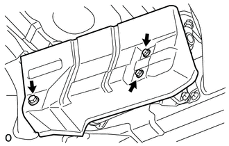
Remove the 3 bolts and insulator from the control unit.
47373B
5.REMOVE CLAMP
Remove the clamp from the 3 height control tubes.
6.DISCHARGE SUSPENSION FLUID PRESSURE
48987
7.REMOVE NO. 7 HEIGHT CONTROL TUBE
48997
8.DISCONNECT REAR NO. 4 HEIGHT CONTROL TUBE
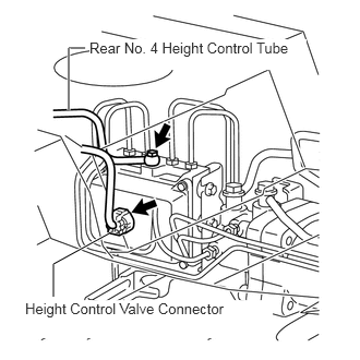
Disconnect the connector.
Remove the union bolt and gasket, then disconnect the rear No. 4 height control tube from the control valve.
48985
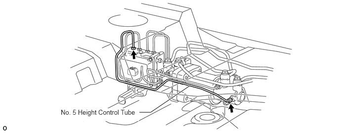
9.REMOVE NO. 5 HEIGHT CONTROL TUBE
Using a union nut wrench, remove the No. 5 height control tube from the control valve and center cylinder.
48995E
10.REMOVE NO. 5 HEIGHT CONTROL TUBE LH
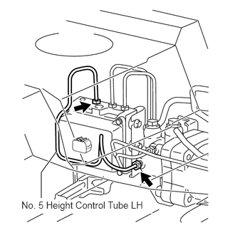
Using a union nut wrench, remove the No. 5 height control tube LH from the control valve and center cylinder.
48986
11.REMOVE NO. 6 HEIGHT CONTROL TUBE
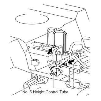
Using a union nut wrench, remove the No. 6 height control tube from the control valve and center cylinder.
48996D
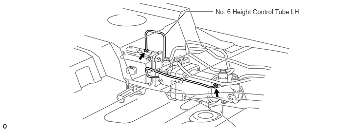
12.REMOVE NO. 6 HEIGHT CONTROL TUBE LH
Using a union nut wrench, remove the No. 6 height control tube LH from the control valve and center cylinder.
48940
13.REMOVE NO. 1 HEIGHT CONTROL VALVE ASSEMBLY
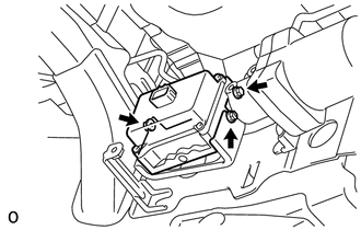
Remove the 3 nuts and control valve.
Remove the 3 bolt holders and 3 bolt cushions from the control valve.