BRAKE SYSTEM (OTHER) BRAKE PEDAL(for RHD) INSTALLATION
PROCEDURE

 1.INSTALL BRAKE PEDAL SUPPORT ASSEMBLY
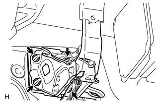
Install the brake pedal support assembly with the 4 nuts.
- Torque:
- 14 N*m (145 kgf*cm, 10 ft.*lbf)
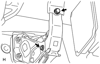
Install the brake pedal support reinforcement set bolt.
- Torque:
- 16 N*m (163 kgf*cm, 12 ft.*lbf)
Tighten the hexagon bolt.
- Torque:
- 23 N*m (239 kgf*cm, 17 ft.*lbf)
- HINT:
-
Hold the bolt in place and tighten the nut.
47264A
2.INSTALL PUSH ROD PIN
Apply a light coat lithium soap base glycol grease to the inner surface of the hole on the brake pedal lever.
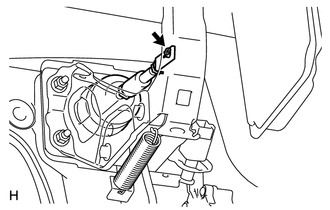
Set the master cylinder push rod clevis in place, insert the push rod pin from the outside of the vehicle and then install a new clip.
84340
3.INSTALL STOP LIGHT SWITCH ASSEMBLY
Install the stop light switch (See page Vehicle Exterior>LIGHTING (EXT)>STOP LIGHT SWITCH>INSTALLATION).
Connect the stop light switch connector.
73900
4.INSTALL DRIVER SIDE KNEE AIRBAG ASSEMBLY
55432D
5.INSTALL LOWER NO. 1 INSTRUMENT PANEL FINISH PANEL
55606
6.INSTALL NO. 1 INSTRUMENT PANEL UNDER COVER SUB-ASSEMBLY
62111C
7.INSTALL COWL SIDE TRIM BOARD RH
67913B
8.INSTALL FRONT DOOR SCUFF PLATE RH
9.WARM UP CABLE TO NEGATIVE BATTERY TERMINAL
- NOTICE:
-
When disconnecting the cable, some systems need to be initialized after the cable is reconnected (See page General>INTRODUCTION>REPAIR INSTRUCTION>INITIALIZATION).
10.CHECK BRAKE PEDAL HEIGHT
11.CHECK PEDAL FREE PLAY
12.CHECK PEDAL RESERVE DISTANCE