WINCH WINCH SYSTEM ON-VEHICLE INSPECTION
PROCEDURE

 38640
1.INSPECT REMOTE CONTROL SWITCH ASSEMBLY
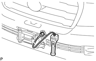
Connect the remote control switch connector.
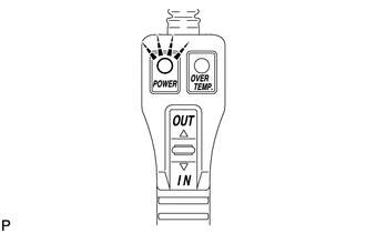
Turn the engine switch on (IG) and check that the power indicator light illuminates.
Press the winch control switch, and check that the winch operates.
- NOTICE:
-
Be careful not to tighten or strain the winch wire.
Turn the engine switch off.
53806
2.REMOVE FRONT FENDER SPLASH SHIELD SUB-ASSEMBLY LH
53805
3.REMOVE FRONT FENDER SPLASH SHIELD SUB-ASSEMBLY RH
53292A
4.REMOVE UPPER RADIATOR SUPPORT SEAL
for Gasoline Engine:
Remove the upper radiator support seal (See page Engine / Hybrid System>1GR-FE (ENGINE MECHANICAL)>ENGINE ASSEMBLY>REMOVAL).
for Diesel Engine:
Remove the upper radiator support seal (See page Engine / Hybrid System>1VD-FTV (ENGINE MECHANICAL)>ENGINE ASSEMBLY>REMOVAL).
52049
5.REMOVE FRONT BUMPER WINCH COVER SUB-ASSEMBLY
53111
6.REMOVE RADIATOR GRILLE ASSEMBLY
52119A
7.REMOVE FRONT BUMPER COVER
8.INSPECT OVERHEAT TEMPERATURE INDICATOR
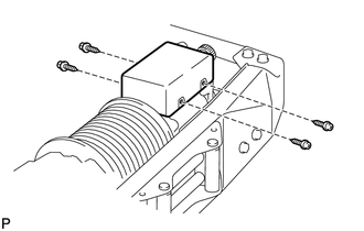
Remove the 4 screws and cover.
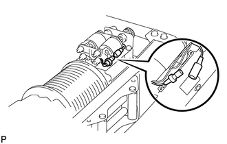
Disconnect the motor relay connector.
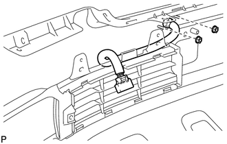
Remove the 2 nuts.
Pull the bumper side winch control wire out of the bumper.
Connect the bumper side winch control wire connector to the vehicle side winch control wire connector.
Connect the bumper side winch control wire connector to the winch control switch connector.
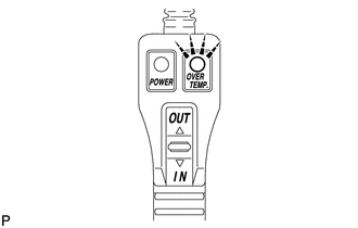
Turn the engine switch on (IG) and check that the overheat temperature indicator light illuminates and the buzzer sounds.
Turn the engine switch off.
Disconnect the bumper side winch control wire connector from the winch control switch connector.
Disconnect the bumper side winch control wire connector from the vehicle side winch control wire connector.
Pass the bumper side winch control wire through the bumper.
Install the 2 nuts.
Connect the motor relay connector.
Install the cover with the 4 screws.
52119A
9.INSTALL FRONT BUMPER COVER
53111
10.INSTALL RADIATOR GRILLE ASSEMBLY
52049
11.INSTALL FRONT BUMPER WINCH COVER SUB-ASSEMBLY
53292A
12.INSTALL UPPER RADIATOR SUPPORT SEAL
for Gasoline Engine:
Install the upper radiator support seal (See page Engine / Hybrid System>1GR-FE (ENGINE MECHANICAL)>ENGINE ASSEMBLY>INSTALLATION).
for Diesel Engine:
Install the upper radiator support seal (See page Engine / Hybrid System>1VD-FTV (ENGINE MECHANICAL)>ENGINE ASSEMBLY>INSTALLATION).
53805
13.INSTALL FRONT FENDER SPLASH SHIELD SUB-ASSEMBLY RH
53806
14.INSTALL FRONT FENDER SPLASH SHIELD SUB-ASSEMBLY LH