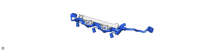
V35A-FTS FUEL FUEL INJECTOR(for Port Injection) REMOVAL
CAUTION / NOTICE / HINT
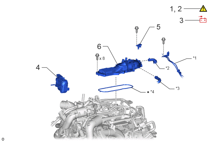
| Procedure | Part Name Code |

|

|

|
|
|---|---|---|---|---|---|
| 1 | DISCHARGE FUEL SYSTEM PRESSURE | - | ( ) |
- | - |
| 2 | PRECAUTION | - | () |
- | - |
| 3 | DISCONNECT CABLE FROM NEGATIVE BATTERY TERMINAL | - | - | - | - |
| 4 | THROTTLE WITH THROTTLE POSITION SENSOR BODY ASSEMBLY | 22030 | - | - | - |
| 5 | NO. 3 TURBO PRESSURE SENSOR | 89421Q | - | - | - |
| 6 | INTAKE AIR SURGE TANK ASSEMBLY | 17190 | - | - | - |
| *1 | NO. 3 TURBO WATER PIPE SUB-ASSEMBLY | *2 | VENTILATION HOSE |
| *3 | NO. 3 VAPOR FEED HOSE | *4 | GASKET |
| ● | Non-reusable part | - | - |
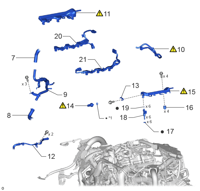
| Procedure | Part Name Code |
|
|
|
|
|---|---|---|---|---|---|
| 7 | WATER HOSE SUB-ASSEMBLY | 87209 | - | - | - |
| 8 | NO. 14 WATER BY-PASS HOSE | 1629A | - | - | - |
| 9 | NO. 5 WATER BY-PASS PIPE | 16289 | - | - | - |
| 10 | FUEL TUBE SUB-ASSEMBLY | 23910A | () |
- | - |
| 11 | NO. 1 FUEL DELIVERY PIPE SUB-ASSEMBLY RH | 23807L | () |
- | - |
| 12 | NO. 6 WATER BY-PASS PIPE | 1628A | - | - | - |
| 13 | NO. 2 FUEL PRESSURE SENSOR HOLDER | 23851A | - | - | - |
| 14 | NO. 2 FUEL PRESSURE SENSOR | 89458H | () |
- | - |
| 15 | NO. 1 FUEL DELIVERY PIPE SUB-ASSEMBLY LH | 23808A | () |
- | - |
| 16 | FUEL DELIVERY SPACER | 23891 | - | - | - |
| 17 | INJECTOR VIBRATION INSULATOR | 23291 | - | - | - |
| 18 | PORT FUEL INJECTOR ASSEMBLY | 23250F | - | - | - |
| 19 | FUEL INJECTOR O-RING | 23250G | - | - | - |
| 20 | NO. 7 ENGINE WIRE | 82127D | - | - | - |
| 21 | NO. 8 ENGINE WIRE | 82128A | - | - | - |
| *1 | O-RING | - | - |
| ● | Non-reusable part | - | - |
CAUTION / NOTICE / HINT
The necessary procedures (adjustment, calibration, initialization or registration) that must be performed after parts are removed and installed, or replaced during port fuel injector assembly removal/installation are shown below.
| Replaced Part or Performed Procedure | Necessary Procedure | Effect/Inoperative Function when Necessary Procedure not Performed | Link |
|---|---|---|---|
| Battery terminal is disconnected/reconnected | Memorize steering angle neutral point | Parking assist monitor system | () |
| Multi-terrain monitor system | () |
||
| Panoramic view monitor system | () |
||
| Replacement of port fuel injector assembly | Inspection After Repair |
·
Poor idle, etc.
·
Engine start function, etc. |
() |
- HINT:
-
When the cable is disconnected/reconnected to the battery terminal, systems temporarily stop operating. However, each system has a function that completes learning the first time the system is used.
-
·
Learning completes when vehicle is driven
Effect/Inoperative Function When Necessary Procedures are not Performed Necessary Procedures Link Stop and start system Drive the vehicle until stop and start control is permitted (approximately 5 to 60 minutes) ( )Lighting system (EXT) Cornering lights Drive the vehicle straight ahead at 35 km/h (22 mph) or more for 5 seconds or more. ( )Pre-collision system Lane tracing assist system Lane departure alert system Adaptive high beam system
·Learning completes when vehicle is operated normally
Effect/Inoperative Function When Necessary Procedures are not Performed Necessary Procedures Link Power back door system Fully close the back door by hand.
- HINT:
-
Initialization is not necessary if the above procedures are performed while the back door is closed.
( )Air conditioning system After the ignition switch is turned to ON, the servo motor and expansion valve standard position is recognized. -
- CAUTION:
-
·
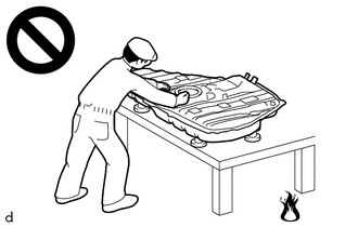
Never perform work on fuel system components near any possible ignition sources.
·Vaporized fuel could ignite, resulting in a serious accident.
-
·
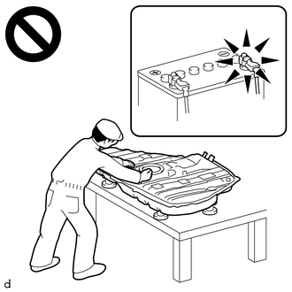
Do not perform work on fuel system components without first disconnecting the cable from the negative (-) battery terminal.
·Sparks could cause vaporized fuel to ignite, resulting in a serious accident.
- NOTICE:
-
This procedure includes the removal of small-head bolts. Refer to Small-Head Bolts of Basic Repair Hint to identify the small-head bolts.
-
Click hereGeneral>INTRODUCTION>REPAIR INSTRUCTION>PRECAUTION
PROCEDURE

 1. DISCHARGE FUEL SYSTEM PRESSURE
2. PRECAUTION
- NOTICE:
-
After turning the ignition switch off, waiting time may be required before disconnecting the cable from the negative (-) battery terminal.
-
Click hereGeneral>SETUP>WHEN DISCONNECTING OR RECONNECTING BATTERY TERMINAL>BEFORE DISCONNECTING BATTERY
3.DISCONNECT CABLE FROM NEGATIVE BATTERY TERMINAL
22030 4.REMOVE THROTTLE WITH THROTTLE POSITION SENSOR BODY ASSEMBLY
89421Q 5.REMOVE NO. 3 TURBO PRESSURE SENSOR
17190 6.REMOVE INTAKE AIR SURGE TANK ASSEMBLY
87209 7.DISCONNECT WATER HOSE SUB-ASSEMBLY
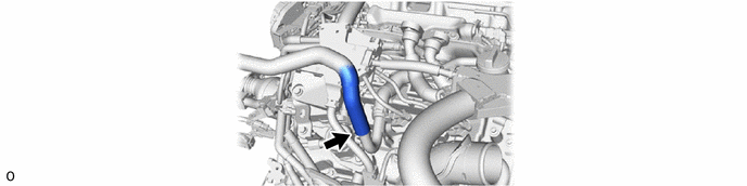
1629A 8.DISCONNECT NO. 14 WATER BY-PASS HOSE
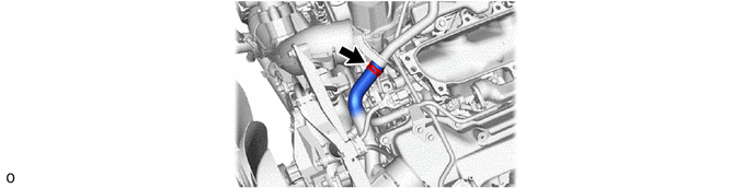
16289 9.REMOVE NO. 5 WATER BY-PASS PIPE
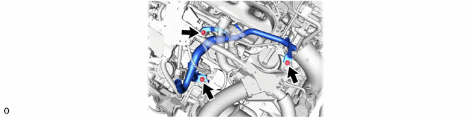
23910A 10.DISCONNECT FUEL TUBE SUB-ASSEMBLY
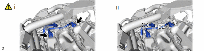
Disconnect the fuel tube sub-assembly from the No. 1 fuel delivery pipe sub-assembly RH and No. 1 fuel delivery pipe sub-assembly LH.
Click hereEngine / Hybrid System>V35A-FTS (FUEL)>FUEL SYSTEM>PRECAUTION
Disconnect the fuel tube sub-assembly from the 2 fuel hose clamps.
23807L 11.REMOVE NO. 1 FUEL DELIVERY PIPE SUB-ASSEMBLY RH
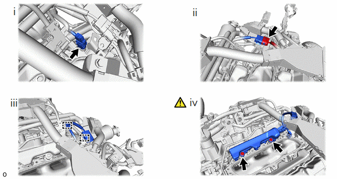
Disconnect the connector from the fuel pressure sensor.
Disconnect the connector from the No. 7 engine wire.
Detach the 2 clamps and disconnect the No. 7 engine wire from the wire harness clamp bracket and cylinder head cover sub-assembly RH.
Remove the 2 bolts and No. 1 fuel delivery pipe sub-assembly RH from the intake manifold.
- NOTICE:
-
Do not to drop the port fuel injector assembly.
1628A 12.DISCONNECT NO. 6 WATER BY-PASS PIPE
23851A 13.REMOVE NO. 2 FUEL PRESSURE SENSOR HOLDER
89458H 14.REMOVE NO. 2 FUEL PRESSURE SENSOR
23808A 15.REMOVE NO. 1 FUEL DELIVERY PIPE SUB-ASSEMBLY LH
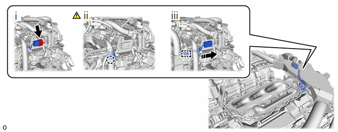
Disconnect the connector from the No. 8 engine wire.
Detach the claw and open the cover of the connector holder.
Detach the clamp and disconnect the No. 8 engine wire from the connector holder.
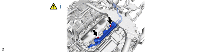
Remove the 2 bolts and No. 1 fuel delivery pipe sub-assembly LH from the intake manifold.
- NOTICE:
-
Do not to drop the port fuel injector assembly.
23891 16.REMOVE FUEL DELIVERY SPACER
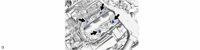
23291 17.REMOVE INJECTOR VIBRATION INSULATOR
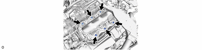
23250F 18.REMOVE PORT FUEL INJECTOR ASSEMBLY
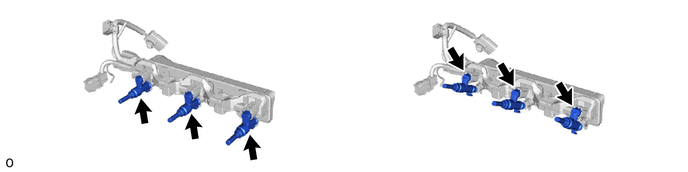
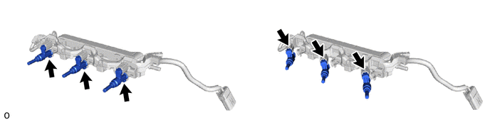
23250G 19.REMOVE FUEL INJECTOR O-RING
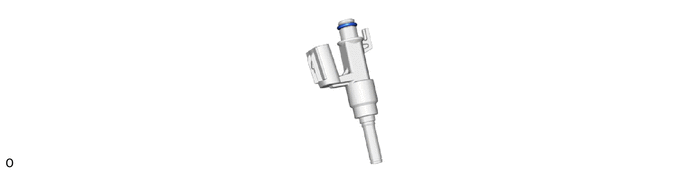
82127D 20.REMOVE NO. 7 ENGINE WIRE
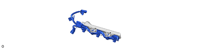
82128A 21.REMOVE NO. 8 ENGINE WIRE