1GR-FE FUEL FUEL PUMP INSTALLATION
CAUTION / NOTICE / HINT
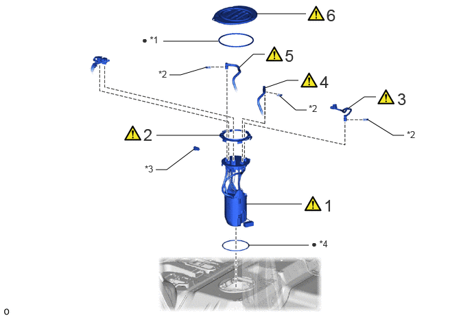
| Procedure | Part Name Code |

|

|

|
|
|---|---|---|---|---|---|
| 1 | FUEL SUCTION WITH PUMP AND GAUGE TUBE ASSEMBLY | 77020A | ( ) |
- | - |
| 2 | FUEL PUMP GAUGE RETAINER (for RH Side) | 77144 | () |
- | - |
| 3 | NO. 2 FUEL MAIN TUBE SUB-ASSEMBLY | 77206C | () |
- | - |
| 4 | FUEL TANK RETURN TUBE | 77204A | () |
- | - |
| 5 | FUEL TANK MAIN TUBE SUB-ASSEMBLY | 77209C | () |
- | - |
| 6 | REAR FLOOR SERVICE HOLE COVER (for RH Side) | 58325E | () |
- | - |
| *1 | BUTYL TAPE | *2 | TUBE JOINT CLIP |
| *3 | NO. 1 FUEL TUBE CLAMP | *4 | GASKET |
| ● | Non-reusable part | - | - |
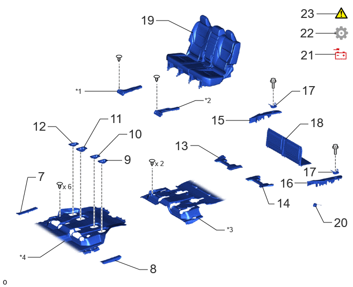
| Procedure | Part Name Code |
|
|
|
|
|---|---|---|---|---|---|
| 7 | REAR DOOR SCUFF PLATE RH | 67917C | - | - | - |
| 8 | REAR DOOR SCUFF PLATE LH | 67918D | - | - | - |
| 9 | REAR NO. 4 SEAT PROTECTOR | 71F95 | - | - | - |
| 10 | REAR NO. 3 SEAT PROTECTOR | 71695Y | - | - | - |
| 11 | REAR NO. 2 SEAT PROTECTOR | 71695T | - | - | - |
| 12 | REAR NO. 1 SEAT PROTECTOR | 71695S | - | - | - |
| 13 | NO. 2 SEAT NO. 1 LEG COVER RH | 79959G | - | - | - |
| 14 | NO. 2 SEAT NO. 1 LEG COVER LH | 79959J | - | - | - |
| 15 | REAR FLOOR BOARD REAR RH | 58417B | - | - | - |
| 16 | REAR FLOOR BOARD REAR LH | 58418H | - | - | - |
| 17 | ROPE HOOK ASSEMBLY | 66310N | - | - | - |
| 18 | DECK BOARD ASSEMBLY | 58410B | - | - | - |
| 19 | REAR NO. 1 SEAT ASSEMBLY | - | - | - | - |
| 20 | FUEL TANK CAP ASSEMBLY | 77310A | - | - | - |
| 21 | CONNECT CABLE TO NEGATIVE BATTERY TERMINAL | - | - | - | - |
| 22 | INITIALIZATION AFTER RECONNECTING BATTERY TERMINAL | - | - | - | () |
| 23 | INSPECT FOR FUEL LEAK | - | () |
- | - |
| *1 | NO. 4 REAR SIDE AIR DUCT | *2 | NO. 6 REAR SIDE AIR DUCT |
| *3 | REAR FLOOR SILENCER | *4 | FRONT FLOOR CARPET ASSEMBLY |
CAUTION / NOTICE / HINT
- HINT:
-
Perform "Inspection After Repairs" after replacing the fuel suction with pump and gauge tube assembly.
-
Click hereEngine / Hybrid System>1GR-FE (ENGINE CONTROL)>SFI SYSTEM>INITIALIZATION
PROCEDURE

 77020A 1.INSTALL FUEL SUCTION WITH PUMP AND GAUGE TUBE ASSEMBLY
|
|
|
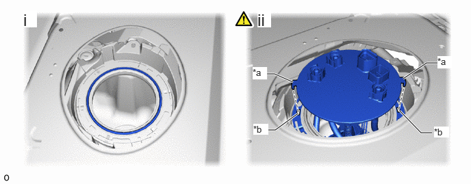
| *a | Protrusion | *b | Notch |
Install a new gasket to the fuel tank sub-assembly.
Align the protrusions of the fuel suction with pump and gauge tube assembly with the notches in the fuel tank sub-assembly.
- NOTICE:
-
Be careful not to bend the arm of the fuel sender gauge.
77144 2.INSTALL FUEL PUMP GAUGE RETAINER (for RH Side)
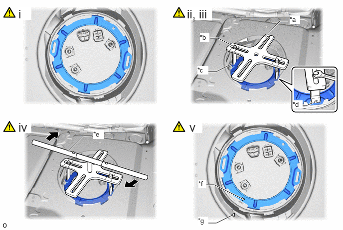
| *a | SST (Plate) | *b | SST (Bolt) |
| *c | SST (Claw) | *d | Insertion Point |
| *e | SST (Handle) | *f | Triangle Mark (Fuel Pump Gauge Retainer) |
| *g | Triangle Mark (Fuel Tank Sub-assembly) | - | - |
While pressing down on the fuel suction with pump and gauge tube assembly, temporarily install the fuel pump gauge retainer.
Temporarily install SST (plate) and SST (claw) to the fuel pump gauge retainer.
- SST
-
09808-14031 (09808-01030, 09808-01090)
09808-01071
- HINT:
-
Securely insert the ends of SST (claw) into the insertion points in the fuel pump gauge retainer.
While firmly pressing SST (claw) into the insertion points in the fuel pump gauge retainer, tighten SST (bolt).
Install SST (handle) to SST (plate).
- SST
-
09808-14031 (09808-01010)
Using SST, rotate the fuel pump gauge retainer so that the triangle mark on the fuel pump gauge retainer is aligned with the triangle mark on the fuel tank sub-assembly to install the fuel suction with pump and gauge tube assembly to the fuel tank sub-assembly.
- NOTICE:
-
·
Do not use any tools other than specified as this may result in damage to the fuel pump gauge retainer or fuel tank sub-assembly.
·Do not press down on SST excessively as this may make the fuel pump gauge retainer hard to rotate, and may damage components.
·Make sure to rotate SST (handle) horizontally. If it is rotated at an angle, SST may come off.
·Do not spin SST too fast or use an impact wrench as this may result in damage to components.
·If SST comes off of the fuel pump gauge retainer, loosen SST (bolt) and reinstall SST.
·Make sure that the gasket does not come off.
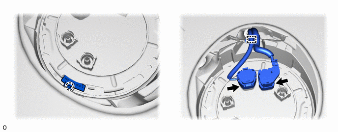
77206C 3.CONNECT NO. 2 FUEL MAIN TUBE SUB-ASSEMBLY
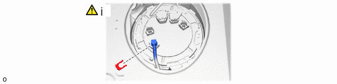
Push the fuel tube joint of the No. 2 fuel main tube sub-assembly, and install the tube joint clip.
- NOTICE:
-
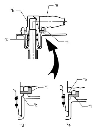 0.969,0.76 0.729,0.385 0.729,0.385 0.573,0.385 false 1.656,0.573 1.729,0.198 1.729,0.198 1.896,0.198 false 1.625,1.083 2.094,1.479 2.094,1.479 2.26,1.479 true 1.104,3.24 1.375,3.094 1.375,3.094 1.542,3.094 false 2.438,3.271 2.75,2.813 2.75,2.813 2.917,2.813 true 0.792,3.385 1.021,3.729 1.021,3.729 1.188,3.729 true 2.594,3.396 2.938,3.781 2.938,3.781 3.104,3.781 false 1.01,1.396 0.344,1.396 true 1,1.229 0.583,1.219 0.583,1.219 0.583,1.385 true 0.375,0.292 0.594,0.469 0.219,0.177 10 false *b 1.927,0.094 2.146,0.271 0.219,0.177 10 false *a 2.313,1.406 2.531,1.583 0.219,0.177 10 false *1 0.156,1.302 0.375,1.479 0.219,0.177 10 false *c 1.573,3 1.792,3.177 0.219,0.177 10 false *1 2.948,2.729 3.167,2.906 0.219,0.177 10 false *b 0.719,4.354 0.938,4.531 0.219,0.177 10 false *d 2.375,4.344 2.594,4.521 0.219,0.177 10 false *e 1.198,3.635 1.417,3.813 0.219,0.177 10 false *b 3.135,3.688 3.354,3.865 0.219,0.177 10 false *1
*1 Tube Joint Clip *a Nylon Tube *b Fuel Tube Joint *c O-ring *d Correct *e Incorrect
-
·
Check that there are no scratches or foreign matter around the connecting parts of the fuel tube joint and plug before performing this work.
·Check that the fuel tube joint is securely inserted to the end.
·Check that the tube joint clip is on the collar of the fuel tube joint.
·After installing the tube joint clip, check that the No. 2 fuel main tube sub-assembly is securely connected by pulling on it.
77204A 4.CONNECT FUEL TANK RETURN TUBE
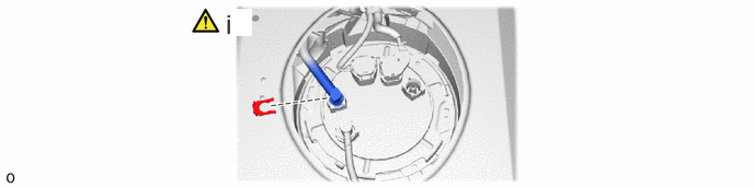
Push the fuel tube joint of the fuel tank return tube, and install the tube joint clip.
- NOTICE:
-
0.969,0.76 0.729,0.385 0.729,0.385 0.573,0.385 false 1.656,0.573 1.729,0.198 1.729,0.198 1.896,0.198 false 1.625,1.083 2.094,1.479 2.094,1.479 2.26,1.479 true 1.104,3.24 1.375,3.094 1.375,3.094 1.542,3.094 false 2.438,3.271 2.75,2.813 2.75,2.813 2.917,2.813 true 0.792,3.385 1.021,3.729 1.021,3.729 1.188,3.729 true 2.594,3.396 2.938,3.781 2.938,3.781 3.104,3.781 false 1.01,1.396 0.344,1.396 true 1,1.229 0.583,1.219 0.583,1.219 0.583,1.385 true 0.375,0.292 0.594,0.469 0.219,0.177 10 false *b 1.927,0.094 2.146,0.271 0.219,0.177 10 false *a 2.313,1.406 2.531,1.583 0.219,0.177 10 false *1 0.156,1.302 0.375,1.479 0.219,0.177 10 false *c 1.573,3 1.792,3.177 0.219,0.177 10 false *1 2.948,2.729 3.167,2.906 0.219,0.177 10 false *b 0.719,4.354 0.938,4.531 0.219,0.177 10 false *d 2.375,4.344 2.594,4.521 0.219,0.177 10 false *e 1.198,3.635 1.417,3.813 0.219,0.177 10 false *b 3.135,3.688 3.354,3.865 0.219,0.177 10 false *1
*1 Tube Joint Clip *a Nylon Tube *b Fuel Tube Joint *c O-ring *d Correct *e Incorrect
-
·
Check that there are no scratches or foreign matter around the connecting parts of the fuel tube joint and plug before performing this work.
·Check that the fuel tube joint is securely inserted to the end.
·Check that the tube joint clip is on the collar of the fuel tube joint.
·After installing the tube joint clip, check that the fuel tank return rube is securely connected by pulling on it.
77209C 5.CONNECT FUEL TANK MAIN TUBE SUB-ASSEMBLY
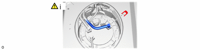
Push the fuel tube joint of the fuel tank main tube sub-assembly, and install the tube joint clip.
- NOTICE:
-
0.969,0.76 0.729,0.385 0.729,0.385 0.573,0.385 false 1.656,0.573 1.729,0.198 1.729,0.198 1.896,0.198 false 1.625,1.083 2.094,1.479 2.094,1.479 2.26,1.479 true 1.104,3.24 1.375,3.094 1.375,3.094 1.542,3.094 false 2.438,3.271 2.75,2.813 2.75,2.813 2.917,2.813 true 0.792,3.385 1.021,3.729 1.021,3.729 1.188,3.729 true 2.594,3.396 2.938,3.781 2.938,3.781 3.104,3.781 false 1.01,1.396 0.344,1.396 true 1,1.229 0.583,1.219 0.583,1.219 0.583,1.385 true 0.375,0.292 0.594,0.469 0.219,0.177 10 false *b 1.927,0.094 2.146,0.271 0.219,0.177 10 false *a 2.313,1.406 2.531,1.583 0.219,0.177 10 false *1 0.156,1.302 0.375,1.479 0.219,0.177 10 false *c 1.573,3 1.792,3.177 0.219,0.177 10 false *1 2.948,2.729 3.167,2.906 0.219,0.177 10 false *b 0.719,4.354 0.938,4.531 0.219,0.177 10 false *d 2.375,4.344 2.594,4.521 0.219,0.177 10 false *e 1.198,3.635 1.417,3.813 0.219,0.177 10 false *b 3.135,3.688 3.354,3.865 0.219,0.177 10 false *1
*1 Tube Joint Clip *a Nylon Tube *b Fuel Tube Joint *c O-ring *d Correct *e Incorrect
-
·
Check that there are no scratches or foreign matter around the connecting parts of the fuel tube joint and plug before performing this work.
·Check that the fuel tube joint is securely inserted to the end.
·Check that the tube joint clip is on the collar of the fuel tube joint.
·After installing the tube joint clip, check that the fuel tank main tube sub-assembly is securely connected by pulling on it.
58325E 6.INSTALL REAR FLOOR SERVICE HOLE COVER (for RH Side)
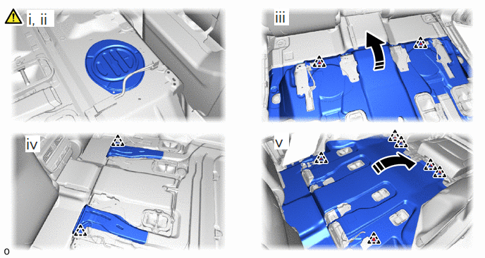
Remove any remaining butyl tape from the rear floor service hole cover and body.
Install the rear floor service hole cover with new butyl tape.
- NOTICE:
-
Securely install the rear floor service hole cover.
Return the rear floor silencer and attach the 2 clips.
Install the No. 4 rear side air duct and No. 6 rear side air duct and attach the 2 clips.
Return the front floor carpet assembly and attach the 6 clips.
67917C 7.INSTALL REAR DOOR SCUFF PLATE RH
67918D 8.INSTALL REAR DOOR SCUFF PLATE LH
71F95 9.INSTALL REAR NO. 4 SEAT PROTECTOR
71695Y 10.INSTALL REAR NO. 3 SEAT PROTECTOR
71695T 11.INSTALL REAR NO. 2 SEAT PROTECTOR
71695S 12.INSTALL REAR NO. 1 SEAT PROTECTOR
79959G 13.INSTALL NO. 2 SEAT NO. 1 LEG COVER RH
79959J 14.INSTALL NO. 2 SEAT NO. 1 LEG COVER LH
58417B 15.INSTALL REAR FLOOR BOARD REAR RH
58418H 16.INSTALL REAR FLOOR BOARD REAR LH
66310N 17.INSTALL ROPE HOOK ASSEMBLY
58410B 18.INSTALL DECK BOARD ASSEMBLY
19.INSTALL REAR NO. 1 SEAT ASSEMBLY
for LH Side:
Click hereVehicle Interior>SEAT>REAR NO. 1 SEAT ASSEMBLY (for LH Side)>INSTALLATION
for 60/40 Split Seat Type RH Side:
Click hereVehicle Interior>SEAT>REAR NO. 1 SEAT ASSEMBLY (for 60/40 Split Seat Type RH Side)>INSTALLATION
for 40/20/40 Split Seat Type RH Side:
Click hereVehicle Interior>SEAT>REAR NO. 1 SEAT ASSEMBLY (for 40/20/40 Split Seat Type RH Side)>INSTALLATION
77310A 20.INSTALL FUEL TANK CAP ASSEMBLY
21.CONNECT CABLE TO NEGATIVE BATTERY TERMINAL
22. INITIALIZATION AFTER RECONNECTING BATTERY TERMINAL
Click hereGeneral>SETUP>WHEN DISCONNECTING OR RECONNECTING BATTERY TERMINAL>WORK PROCEDURE
- HINT:
-
When disconnecting and reconnecting the battery, there is an automatic learning function that completes learning when the respective system is used.
-
Click hereGeneral>SETUP>WHEN DISCONNECTING OR RECONNECTING BATTERY TERMINAL>AUTOMATIC LEARNING CHART
23.INSPECT FOR FUEL LEAK