Home › Engine / Hybrid System › 1GR-FE (COOLING) › THERMOSTAT
RM38G0E _51 Engine / Hybrid System _101532 1GR-FE COOLING _0470523 THERMOSTAT A

1GR-FE COOLING  THERMOSTAT  INSTALLATION  


CAUTION / NOTICE / HINT
COMPONENTS (INSTALLATION)
A488707N01
0.271,1.521 0.927,1.708 0.656,0.188 3.219,2.458 4.198,2.646 0.979,0.188 1.604,2.813 2.583,3 0.979,0.188 3.479,4.469 4.198,4.656 0.719,0.188 4.958,4.417 5.677,4.604 0.719,0.188 0.135,0.594 3.083,1.802 2.948,1.208 4.969,3.573 5.135,3.969 5.135,3.969 5.302,3.969 false 1.938,3.49 2.354,3.49 false 0.938,2.844 1.302,2.844 false 1.875,2.521 2.083,2.521 2.083,2.521 2.083,2.813 false 2.177,1.24 2.594,1.24 false 6.479,0.208 6.896,0.208 false 2.99,2.583 2.99,2.906 2.99,2.906 3.188,2.906 false 0.479,3.5 0.896,3.5 false 2.26,4.177 2.51,4.177 true 3.479,2.125 3.729,2.125 3.729,2.125 3.729,2.458 false 0.594,1.521 0.594,1.188 0.594,1.188 0.76,1.188 false 3.229,4.396 3.229,4.563 3.229,4.563 3.479,4.563 false 4.708,4.344 4.708,4.51 4.708,4.51 4.958,4.51 false 0.854,2.375 1.26,2.375 false 6.469,0.635 6.885,0.635 false 0.875,2 1.292,2 false 4.146,0.583 4.563,0.583 false 1.76,3.344 2.125,3.635 0.365,0.292 18 false 9 5.365,3.802 5.615,4.125 0.25,0.323 18 false 8 0.75,2.677 1,3 0.25,0.323 18 false 2 0.635,2.219 0.885,2.542 0.25,0.323 18 false 1 2.885,1.083 3.135,1.406 0.25,0.323 18 false 3 4.885,0.448 5.167,0.708 0.281,0.26 18 false 4 6.292,0.063 6.583,0.344 0.292,0.281 18 false 7 3.24,2.75 3.49,3.073 0.25,0.323 18 false 5 0.792,1.24 1.073,1.427 0.281,0.188 10 false x 3 4.802,4.198 5.083,4.385 0.281,0.188 10 false x 2 3.323,4.25 3.604,4.438 0.281,0.188 10 false x 5 0.313,3.417 0.563,3.74 0.25,0.323 10 false *2 1.99,4.438 2.271,4.625 0.281,0.188 10 false x 2 1.219,3.99 1.5,4.177 0.281,0.188 10 false x 2 2.573,4.104 2.823,4.427 0.25,0.323 10 false *1 0.323,1.552 0.927,1.719 0.604,0.167 8 false 10 (102, 7) 3.26,2.479 4.271,2.646 1.01,0.167 8 false 7.0 (71, 62 in.*lbf) 1.656,2.833 2.667,3 1.01,0.167 8 false 9.0 (92, 80 in.*lbf) 3.531,4.5 4.208,4.698 0.677,0.198 8 false 29 (296, 21) 5.01,4.438 5.688,4.635 0.677,0.198 8 false 29 (296, 21) 6.292,0.49 6.583,0.771 0.292,0.281 18 false 6 1.76,2.573 2.042,2.76 0.281,0.188 10 false x 3 3.281,2.219 3.563,2.406 0.281,0.188 10 false x 2 1.354,1.906 1.635,2.094 0.281,0.188 10 false ● 0.198,0.635 0.521,0.854 0.323,0.219 12 false *A

Procedure Part Name Code
Z101186

Z101188

Z101187

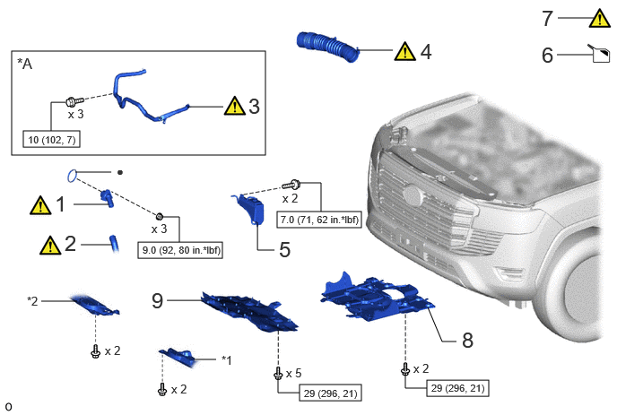
1 WATER INLET SUB-ASSEMBLY WITH THERMOSTAT 16031 - - -
2 NO. 2 RADIATOR HOSE 16572D (Click here) - -
3 AIR TUBE ASSEMBLY 17360G (Click here) - -
4 AIR CLEANER HOSE ASSEMBLY 17880 (Click here) - -
5 RADIATOR RESERVE TANK ASSEMBLY 16470 - - -
6 ADD ENGINE COOLANT - - (Click here) -
7 INSPECT FOR COOLANT LEAK - (Click here) - -
8 NO. 2 ENGINE UNDER COVER ASSEMBLY 51420 - - -
9 NO. 1 ENGINE UNDER COVER ASSEMBLY 51410 - - -

*A w/ Secondary Air Injection System - -
*1 ENGINE SIDE COVER SUB-ASSEMBLY LH *2 ENGINE SIDE COVER SUB-ASSEMBLY RH
V100146

N*m (kgf*cm, ft.*lbf): Specified torque ● Non-reusable part

PROCEDURE

Hide 16031 1.INSTALL WATER INLET SUB-ASSEMBLY WITH THERMOSTAT

a.
A489711C01
0.427,0.073 0.708,0.427 0.281,0.354 18 false i 3.646,0.052 3.927,0.406 0.281,0.354 18 false ii

i.

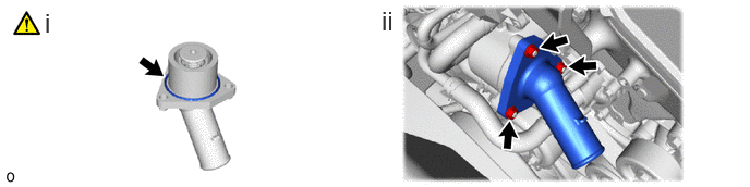
Install a new O-ring to the water inlet sub-assembly with thermostat.

NOTICE:

Keep the O-ring and O-ring fitting surface free of foreign matter.


ii.

Install the water inlet sub-assembly with thermostat with the 3 nuts.

Torque:
9.0 N*m (92 kgf*cm, 80 in.*lbf)


Hide 16572D 2.CONNECT NO. 2 RADIATOR HOSE

a.
A535898C01
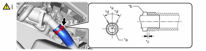
3.906,0.823 4.125,1.406 4.125,1.406 4.281,1.406 true 4.99,0.417 4.802,0.219 4.802,0.219 4.635,0.219 true 3.823,0.198 4.052,0.406 0.229,0.208 10 false *e 3.656,0.333 3.885,0.542 0.229,0.208 10 false *d 5.073,1.375 5.302,1.583 0.229,0.208 10 false *c 4.469,0.135 4.698,0.344 0.229,0.208 10 false *b 4.313,1.313 4.542,1.521 0.229,0.208 10 false *a 0.396,0.083 0.729,0.344 0.333,0.26 18 false i 3.979,0.323 4.208,0.531 0.229,0.208 10 false *d
*a Paint Mark *b Stopper
*c 2.0 to 7.0 mm (0.0787 to 0.276 in.) *d 30°
*e Upper Side - -


i.

Connect the No. 2 radiator hose to the water inlet sub-assembly with thermostat and slide the hose clip to secure it.

NOTICE:
·

Align the hose and the hose clip at the locations shown in the illustration and install them.

·

Make sure the No. 2 radiator hose is securely inserted to the stopper.


Hide 17360G 3.INSTALL AIR TUBE ASSEMBLY (w/ Secondary Air Injection System)

Hide 17880 4.INSTALL AIR CLEANER HOSE ASSEMBLY

Hide 16470 5.INSTALL RADIATOR RESERVE TANK ASSEMBLY

Hide 6.ADD ENGINE COOLANT

Hide 51420 8.INSTALL NO. 2 ENGINE UNDER COVER ASSEMBLY

Hide 51410 9.INSTALL NO. 1 ENGINE UNDER COVER ASSEMBLY