1GR-FE COOLING RADIATOR INSTALLATION
CAUTION / NOTICE / HINT
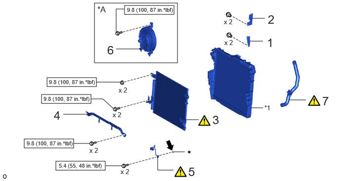
| Procedure | Part Name Code |

|

|

|
|
|---|---|---|---|---|---|
| 1 | NO. 1 RADIATOR TO SUPPORT SEAL | 16561 | - | - | - |
| 2 | UPPER RADIATOR AIR GUIDE PLATE | 16681 | - | - | - |
| 3 | COOLER CONDENSER ASSEMBLY | 884A0 | - | - | - |
| 4 | COOLER BRACKET | - | - | - | - |
| 5 | NO. 2 AIR CONDITIONING TUBE AND ACCESSORY ASSEMBLY | 88710G | ( ) |
- | - |
| 6 | BLOWER ASSEMBLY WITH SHROUD | 88590 | - | - | - |
| 7 | NO. 2 RADIATOR HOSE | 16572D | () |
- | - |
| *A | w/ Condenser Fan | - | - |
| *1 | RADIATOR ASSEMBLY | - | - |

|
N*m (kgf*cm, ft.*lbf): Specified torque | ● | Non-reusable part |

|
Compressor oil ND-OIL 8 or equivalent | - | - |
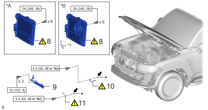
| Procedure | Part Name Code |
|
|
|
|
|---|---|---|---|---|---|
| 8 | RADIATOR WITH COOLER CONDENSER ASSEMBLY | - | () |
- | - |
| 9 | NO. 1 POWER STEERING OIL COOLER SUB-ASSEMBLY | 44402 | - | - | - |
| 10 | NO. 1 COOLER REFRIGERANT DISCHARGE HOSE | 88711 | () |
- | - |
| 11 | AIR CONDITIONING TUBE AND ACCESSORY ASSEMBLY | 88710E | () |
- | - |
| *A | w/o Condenser Fan | *B | w/ Condenser Fan |
| *1 | ENGINE ROOM MAIN WIRE | - | - |
|
|
N*m (kgf*cm, ft.*lbf): Specified torque | ● | Non-reusable part |
|
|
Compressor oil ND-OIL 8 or equivalent | - | - |
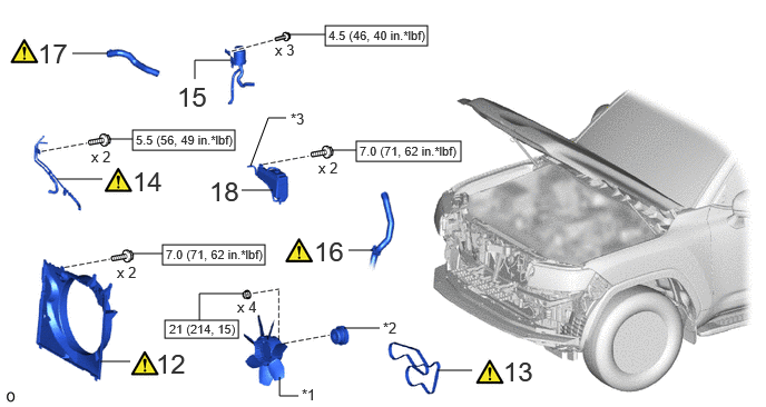
| Procedure | Part Name Code |
|
|
|
|
|---|---|---|---|---|---|
| 12 | FAN SHROUD | 16711 | () |
- | - |
| 13 | FAN AND GENERATOR V BELT | 16361A | () |
- | - |
| 14 | OIL COOLER TUBE SUB-ASSEMBLY | - | () |
- | - |
| 15 | NO. 1 OIL RESERVOIR BRACKET | 44369A | - | - | - |
| 16 | NO. 2 RADIATOR HOSE | 16572D | () |
- | - |
| 17 | NO. 1 RADIATOR HOSE | 16571C | () |
- | - |
| 18 | RADIATOR RESERVE TANK ASSEMBLY | 16470 | - | - | - |
| *1 | FLUID COUPLING ASSEMBLY WITH FAN | *2 | FAN PULLEY |
| 3 | RADIATOR RESERVE TANK HOSE | - | - |
|
|
N*m (kgf*cm, ft.*lbf): Specified torque | - | - |
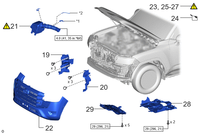
| Procedure | Part Name Code |
|
|
|
|
|---|---|---|---|---|---|
| 19 | NO. 1 RADIATOR AIR GUIDE RH | 16593B | - | - | - |
| 20 | NO. 1 RADIATOR AIR GUIDE LH | 16595B | - | - | - |
| 21 | AIR CLEANER ASSEMBLY WITH AIR CLEANER HOSE | 17700 | () |
- | - |
| 22 | FRONT BUMPER ASSEMBLY | - | - | - | - |
| 23 | CHARGE AIR CONDITIONING SYSTEM WITH REFRIGERANT | - | () |
- | - |
| 24 | ADD ENGINE COOLANT | - | - | () |
- |
| 25 | WARM UP ENGINE | - | () |
- | - |
| 26 | INSPECT FOR REFRIGERANT LEAK | - | () |
- | - |
| 27 | INSPECT FOR COOLANT LEAK | - | () |
- | - |
| 28 | NO. 2 ENGINE UNDER COVER ASSEMBLY | 51420 | - | - | - |
| 29 | NO. 1 ENGINE UNDER COVER ASSEMBLY | 51410 | - | - | - |
| *1 | VENTILATION HOSE | *2 | VACUUM HOSE |
|
|
N*m (kgf*cm, ft.*lbf): Specified torque | - | - |
PROCEDURE

 16561 1.INSTALL NO. 1 RADIATOR TO SUPPORT SEAL
16681 2.INSTALL UPPER RADIATOR AIR GUIDE PLATE
884A0 3.INSTALL COOLER CONDENSER ASSEMBLY
|
|
Click here() |
4.INSTALL COOLER BRACKET
88710G 5.INSTALL NO. 2 AIR CONDITIONING TUBE AND ACCESSORY ASSEMBLY
88590 6.INSTALL BLOWER ASSEMBLY WITH SHROUD (w/ Condenser Fan)
- Torque:
- 9.8 N*m (100 kgf*cm, 87 in.*lbf)
16572D 7.CONNECT NO. 2 RADIATOR HOSE
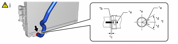
| *a | Paint Mark | *b | Stopper |
| *c | 2.0 to 7.0 mm (0.0787 to 0.276 in.) | *d | 30° |
| *e | Upper Side | *f | RH Side |
Connect the No. 2 radiator hose to the radiator assembly and slide the hose clip to secure it.
- NOTICE:
-
Align the hose and the hose clip at the locations shown in the illustration and install them.
8.INSTALL RADIATOR WITH COOLER CONDENSER ASSEMBLY
w/ Condenser Fan:
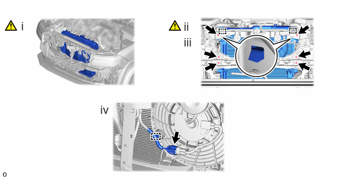
Install the radiator with cooler condenser assembly to the vehicle.
- NOTICE:
-
·
Perform the following procedure with 2 or more people to prevent damage to the radiator with cooler condenser assembly.
·Do not damage the radiator with cooler condenser assembly, cooler pipe or cooling hoses when installing them.
Set the radiator bracket hooks into the radiator support holes.
Install the radiator with cooler condenser assembly with the 6 bolts.
- Torque:
- 24 N*m (245 kgf*cm, 18 ft.*lbf)
Attach the clamp and connect the connector.
w/o Condenser Fan:
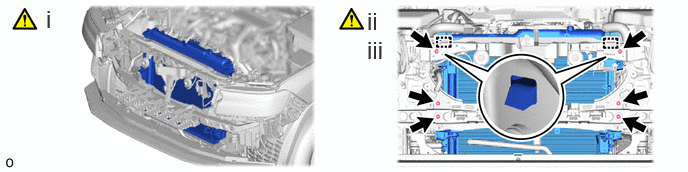
Install the radiator with cooler condenser assembly to the vehicle.
- NOTICE:
-
·
Perform the following procedure with 2 or more people to prevent damage to the radiator with cooler condenser assembly.
·Do not damage the radiator with cooler condenser assembly, cooler pipe or cooling hoses when installing them.
Set the radiator bracket hooks into the radiator support holes.
Install the radiator with cooler condenser assembly with the 6 bolts.
- Torque:
- 24 N*m (245 kgf*cm, 18 ft.*lbf)
44402 9.CONNECT NO. 1 POWER STEERING OIL COOLER SUB-ASSEMBLY
- Torque:
- 12 N*m (122 kgf*cm, 9 ft.*lbf)
88711 10.CONNECT NO. 1 COOLER REFRIGERANT DISCHARGE HOSE
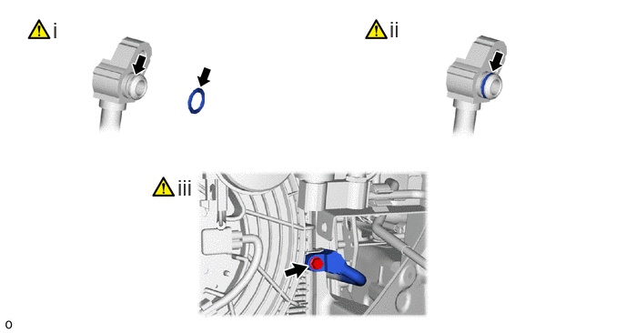
Remove the vinyl tape from the No. 1 cooler refrigerant discharge hose and connecting part of the cooler condenser assembly and then sufficiently apply compressor oil to a new O-ring and the fitting surface of the No. 1 cooler refrigerant discharge hose.
- Compressor Oil:
-
ND-OIL 8 or equivalent
Install the O-ring to the No. 1 cooler refrigerant discharge hose.
- NOTICE:
-
Keep the O-ring and O-ring fitting surface free of foreign matter.
Connect the No. 1 cooler refrigerant discharge hose to the cooler condenser assembly with the bolt.
- Torque:
- 5.4 N*m (55 kgf*cm, 48 in.*lbf)
- NOTICE:
-
Make sure not to cut the O-ring while installing it. (Cut O-rings cannot be installed.)
88710E 11.CONNECT AIR CONDITIONING TUBE AND ACCESSORY ASSEMBLY
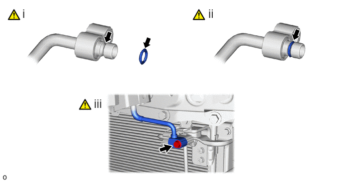
Remove the vinyl tape from the air conditioning tube and accessory assembly and connecting part of the No. 2 air conditioning tube and accessory assembly and then sufficiently apply compressor oil to a new O-ring and the fitting surface of the air conditioning tube and accessory assembly.
- Compressor Oil:
-
ND-OIL 8 or equivalent
Install the O-ring to the air conditioning tube and accessory assembly.
- NOTICE:
-
Keep the O-ring and O-ring fitting surface free of foreign matter.
Connect the air conditioning tube and accessory assembly to the No. 2 air conditioning tube and accessory assembly with the bolt.
- Torque:
- 5.4 N*m (55 kgf*cm, 48 in.*lbf)
- NOTICE:
-
Make sure not to cut the O-ring while installing it. (Cut O-rings cannot be installed.)
16711 12.INSTALL FAN SHROUD
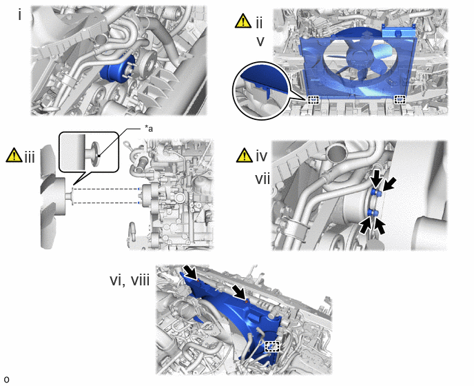
| *a | Paint Mark | - | - |
Install the fan pulley to the engine water pump assembly.
Place the fan shroud together with the fluid coupling assembly with fan between the radiator and engine.
- NOTICE:
-
Be careful not to damage the radiator core.
Align the paint marks on the head of the engine water pump stud bolt with the paint marks of the same color on the outer edge of the fluid coupling flange and set the fluid coupling to the engine water pump assembly.
Temporarily install the fluid coupling assembly with fan to the engine water pump assembly with the 4 nuts. Tighten the nuts as much as possible by hand.
Attach the claws of the fan shroud to the radiator as shown in the illustration.
Install the fan shroud with the 2 bolts.
- Torque:
- 7.0 N*m (71 kgf*cm, 62 in.*lbf)
Tighten the 4 nuts of the fluid coupling assembly with fan.
- Torque:
- 21 N*m (214 kgf*cm, 15 ft.*lbf)
Attach the clamp.
16361A 13.INSTALL FAN AND GENERATOR V BELT
|
|
Click here() |
14.CONNECT OIL COOLER TUBE SUB-ASSEMBLY
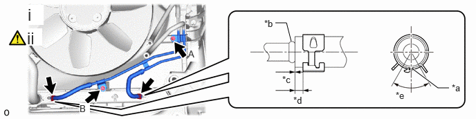
| *a | Paint Mark | *b | Stopper |
| *c | -1.5 to 1.5 mm (-0.0591 to 0.0591 in.) | *d | 2.0 to 7.0 mm (0.0787 to 0.276 in.) |
| *e | 60° | - | - |
Install the oil cooler tube sub-assembly to the fan shroud with the 2 bolts.
- Torque:
- 5.5 N*m (56 kgf*cm, 49 in.*lbf)
- NOTICE:
-
Tightening order: Temporarily install bolt A → Tighten bolt B → Tighten bolt A
Connect the oil cooler tube sub-assembly to the radiator assembly and slide the 2 hose clips to secure it.
- NOTICE:
-
Align the hose and the hose clip at the locations shown in the illustration and install them.
44369A 15.INSTALL NO. 1 OIL RESERVOIR BRACKET
- Torque:
- 4.5 N*m (46 kgf*cm, 40 in.*lbf)
16572D 16.CONNECT NO. 2 RADIATOR HOSE
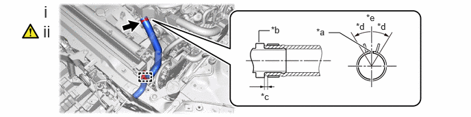
| *a | Paint Mark | *b | Stopper |
| *c | 2.0 to 7.0 mm (0.0787 to 0.276 in.) | *d | 30° |
| *e | Upper Side | - | - |
Attach the clamp.
Connect the No. 2 radiator hose to the water inlet pipe and slide the hose clip to secure it.
- NOTICE:
-
Align the hose and the hose clip at the locations shown in the illustration and install them.
16571C 17.INSTALL NO. 1 RADIATOR HOSE
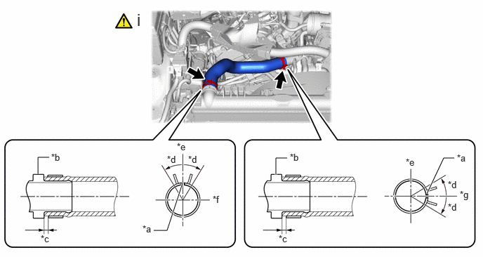
| *a | Paint Mark | *b | Stopper |
| *c | 2.0 to 7.0 mm (0.0787 to 0.276 in.) | *d | 30° |
| *e | Upper Side | *f | RH Side |
| *g | Front Side | - | - |
Install the No. 1 radiator hose to the water outlet pipe and radiator assembly and slide the 2 hose clips to secure it.
- NOTICE:
-
Align the hose and the hose clip at the locations shown in the illustration and install them.
16470 18.INSTALL RADIATOR RESERVE TANK ASSEMBLY
- Torque:
- 7.0 N*m (71 kgf*cm, 62 in.*lbf)
16593B 19.INSTALL NO. 1 RADIATOR AIR GUIDE RH
16595B 20.INSTALL NO. 1 RADIATOR AIR GUIDE LH
17700 21.INSTALL AIR CLEANER ASSEMBLY WITH AIR CLEANER HOSE
22.INSTALL FRONT BUMPER ASSEMBLY
for Standard
Click hereVehicle Exterior>EXTERIOR PANELS / TRIM>FRONT BUMPER (for Standard)>INSTALLATION
for Aero Type
Click hereVehicle Exterior>EXTERIOR PANELS / TRIM>FRONT BUMPER (for Aero Type)>INSTALLATION
23.CHARGE AIR CONDITIONING SYSTEM WITH REFRIGERANT
24.ADD ENGINE COOLANT
25.WARM UP ENGINE
26.INSPECT FOR REFRIGERANT LEAK
27.INSPECT FOR COOLANT LEAK
51420 28.INSTALL NO. 2 ENGINE UNDER COVER ASSEMBLY
51410 29.INSTALL NO. 1 ENGINE UNDER COVER ASSEMBLY