DRIVE SHAFT / PROPELLER SHAFT FRONT PROPELLER SHAFT ASSEMBLY INSTALLATION
CAUTION / NOTICE / HINT
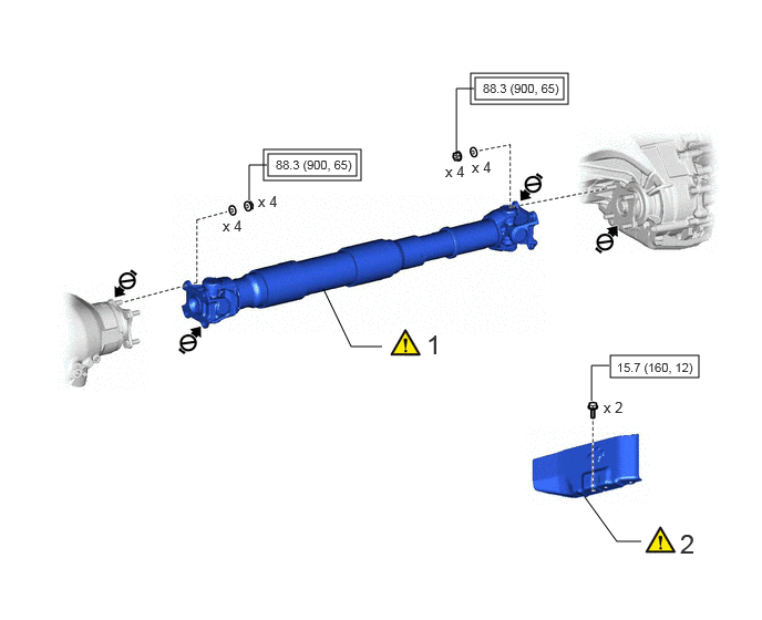
| Procedure | Part Name Code |

|

|

|
|
|---|---|---|---|---|---|
| 1 | FRONT PROPELLER SHAFT ASSEMBLY | 37140 | ( ) |
- | - |
| 2 | NO. 2 PROPELLER SHAFT HEAT INSULATOR | - | () |
- | - |

|
Tightening torque for "Major areas involving basic vehicle performance such as moving/turning/stopping": N*m (kgf*cm, ft.*lbf) |

|
N*m (kgf*cm, ft.*lbf): Specified torque |

|
Do not apply lubricants | - | - |
| Procedure | Part Name Code |
|
|
|
|
|---|---|---|---|---|---|
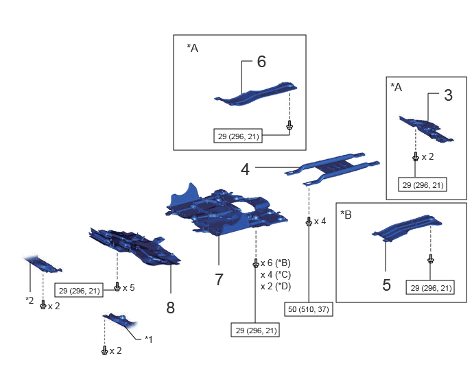
| 3 | TRANSMISSION UNDER COVER ASSEMBLY | 51470 | - | - | - |
| 4 | OIL PAN PROTECTOR ASSEMBLY | 51440 | - | - | - |
| 5 | FRAME UNDER COVER ASSEMBLY LH | 51450C | - | - | - |
| 6 | FRAME UNDER COVER ASSEMBLY RH | 51430A | - | - | - |
| 7 | NO. 2 ENGINE UNDER COVER ASSEMBLY | 51420 | - | - | - |
| 8 | NO. 1 ENGINE UNDER COVER ASSEMBLY | 51410 | - | - | - |
| *A | for V35A-FTS | *B | for V35A-FTS, w/ Cover |
| *C | for V35A-FTS, w/o Cover | *D | for 1GR-FE |
| *1 | ENGINE SIDE COVER SUB-ASSEMBLY LH | *2 | ENGINE SIDE COVER SUB-ASSEMBLY RH |
|
|
N*m (kgf*cm, ft.*lbf): Specified torque | - | - |
PROCEDURE

 37140 1.INSTALL FRONT PROPELLER SHAFT ASSEMBLY
|
|
|
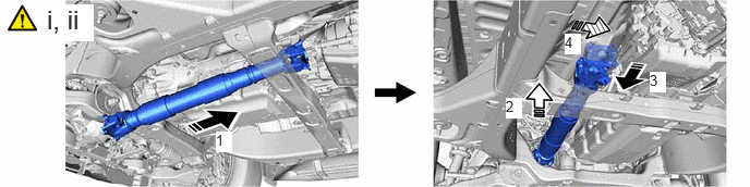
Completely remove any oil, etc. and clean the contact surfaces of the 2 propeller shaft flanges, differential flange and transfer flange.
Temporarily install the front propeller shaft assembly to the transfer and differential in the order shown in the illustration.
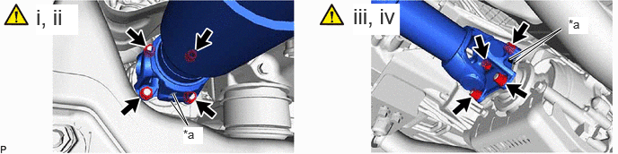
| *a | Matchmark | - | - |
Align the matchmarks on the propeller shaft flange and differential flange.
Install the front propeller shaft assembly with the 4 nuts and 4 washers.
- Torque:
- 88.3 N*m (900 kgf*cm, 65 ft.*lbf)
Align the matchmarks on the propeller shaft flange and transfer flange.
Install the front propeller shaft assembly with the 4 nuts and 4 washers.
- Torque:
- 88.3 N*m (900 kgf*cm, 65 ft.*lbf)
2.INSTALL NO. 2 PROPELLER SHAFT HEAT INSULATOR


|
Front of the Vehicle | - | - |
Install the No. 2 propeller shaft heat insulator with the 2 bolts.
- Torque:
- 15.7 N*m (160 kgf*cm, 12 ft.*lbf)
- NOTICE:
-
Install so that the direction of the arrow points to the front of the vehicle.
51470 3.INSTALL TRANSMISSION UNDER COVER ASSEMBLY (for V35A-FTS)
51440 4.INSTALL OIL PAN PROTECTOR ASSEMBLY
51450C 5.INSTALL FRAME UNDER COVER ASSEMBLY LH (for V35A-FTS, w/ Cover)
51430A 6.INSTALL FRAME UNDER COVER ASSEMBLY RH (for V35A-FTS)
51420 7.INSTALL NO. 2 ENGINE UNDER COVER ASSEMBLY
for V35A-FTS:
Click hereEngine / Hybrid System>V35A-FTS (ENGINE MECHANICAL)>ENGINE ASSEMBLY>INSTALLATION
for 1GR-FE:
Click hereEngine / Hybrid System>1GR-FE (ENGINE MECHANICAL)>ENGINE ASSEMBLY>INSTALLATION
51410 8.INSTALL NO. 1 ENGINE UNDER COVER ASSEMBLY
for V35A-FTS:
Click hereEngine / Hybrid System>V35A-FTS (LUBRICATION)>OIL PAN AND OIL LEVEL SENSOR>INSTALLATION
for 1GR-FE:
Click hereEngine / Hybrid System>1GR-FE (LUBRICATION)>OIL LEVEL SENSOR>INSTALLATION