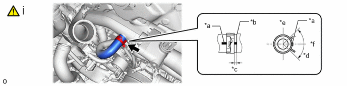
Home › Engine / Hybrid System › V35A-FTS (COOLING) › THERMOSTAT
RM38G0E _51 Engine / Hybrid System _101529 V35A-FTS COOLING _0473312 THERMOSTAT A

V35A-FTS COOLING  THERMOSTAT  INSTALLATION  


CAUTION / NOTICE / HINT
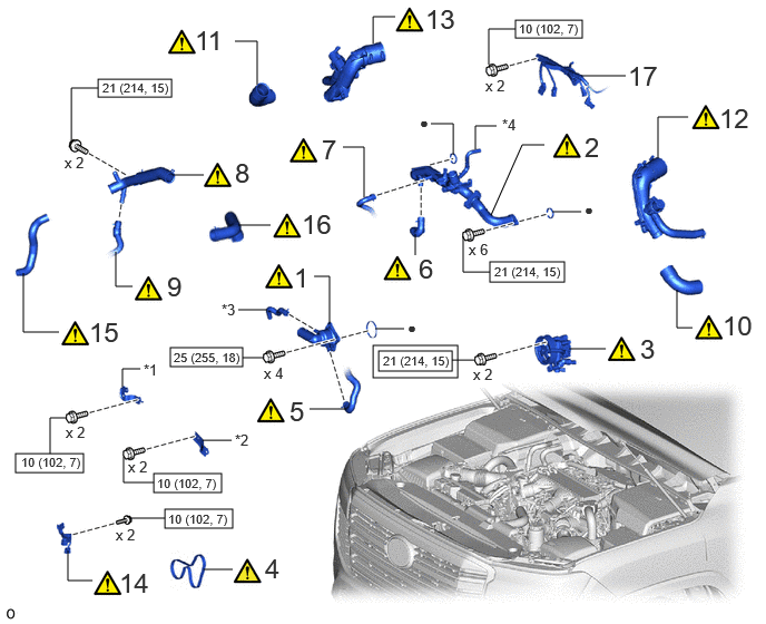
COMPONENTS (INSTALLATION)
A489701N01
4.823,0.188 5.448,0.354 0.625,0.167 0.917,0.74 1.604,0.906 0.688,0.167 1.594,3.25 2.271,3.427 0.677,0.177 1.438,4.427 2.073,4.604 0.635,0.177 0.146,4.24 0.781,4.417 0.635,0.177 4.583,2.448 5.281,2.635 0.698,0.188 1.542,4.76 2.177,4.938 0.635,0.177 3.542,3.281 4.229,3.469 0.688,0.188 3.49,3.229 4.281,3.531 0.792,0.302 2.896,3.823 3.24,3.823 false 6.156,1.479 6.156,1.094 6.156,1.094 6.438,1.094 false 5.438,0.708 5.854,0.708 false 4.594,2.01 4.885,1.354 4.885,1.354 5.094,1.354 false 3.406,1.844 3.406,1.375 3.406,1.375 3.208,1.375 false 2.406,0.792 2.406,0.385 2.406,0.385 2.198,0.385 false 3.49,0.406 3.49,0.156 3.49,0.156 3.698,0.156 false 1.24,2.677 1.083,2.677 1.083,2.677 1.083,2.354 false 3.781,3.073 3.51,3.073 false 3.885,2.385 3.885,2.188 false 3.083,3.031 3.083,2.583 3.083,2.583 2.938,2.583 false 0.667,1.323 0.667,0.823 0.667,0.823 0.917,0.823 false 4.573,0.604 4.573,0.271 4.573,0.271 4.823,0.271 false 4.583,2.542 4.333,2.542 4.333,2.542 4.333,2.208 false 2.469,3.344 2.271,3.344 false 1.146,3.615 1.146,3.448 1.146,3.448 1.313,3.448 false 0.865,5.427 0.635,5.427 0.635,5.427 0.635,5.146 false 1.438,4.51 1.156,4.51 1.156,4.51 1.156,4.271 false 0.469,4.24 0.469,3.906 0.469,3.906 0.625,3.906 false 1.615,1.635 1.906,1.635 false 6.479,3.063 6.333,3.063 6.333,3.063 6.333,2.708 false 2.177,5.323 1.906,5.323 false 0.552,3.104 0.219,3.104 0.219,3.104 0.219,2.552 false 2.229,2.104 2.531,2.104 false 2.167,4.115 1.896,4.115 false 2.5,2.896 2.229,2.896 false 4.448,1.396 4.448,1.177 4.448,1.177 4.646,1.177 false 5.438,1.979 5.167,1.979 false 4.24,1.448 4.24,1.156 4.24,1.156 4.031,1.156 false 5.667,3.26 5.323,3.26 false 1.542,4.844 1.219,4.844 false 4.229,3.365 4.438,3.365 false 1.563,2.531 1.833,2.813 0.271,0.281 18 false 9 2.198,1.469 2.469,1.75 0.271,0.281 18 false 8 1.823,0.229 2.135,0.5 0.313,0.271 18 false 11 3.979,0.031 4.281,0.302 0.302,0.271 18 false 13 5.875,0.563 6.198,0.844 0.323,0.281 18 false 17 6.729,0.958 7.042,1.24 0.313,0.281 18 false 12 6.76,2.896 7.073,3.177 0.313,0.281 18 false 10 5.99,3.115 6.25,3.396 0.26,0.281 18 false 3 5.469,1.229 5.802,1.51 0.333,0.281 18 false 2 3.01,1.25 3.281,1.531 0.271,0.281 18 false 7 2.75,2.448 2.99,2.729 0.24,0.281 18 false 1 1.344,3.375 1.531,3.594 0.188,0.219 10 false *1 2.708,3.698 3.01,3.99 0.302,0.292 18 false 5 0.604,1.438 0.875,1.646 0.271,0.208 10 false x 2 4.542,0.719 4.813,0.927 0.271,0.208 10 false x 2 4.385,2.25 4.656,2.458 0.271,0.208 10 false x 6 2.469,3.406 2.74,3.615 0.271,0.208 10 false x 4 1.625,3.271 2.396,3.469 0.771,0.198 8 false 25 (255, 18) 4.625,2.469 5.323,2.635 0.698,0.167 8 false 21 (214, 15) 4.854,0.198 5.625,0.396 0.771,0.198 8 false 10 (102, 7) 0.958,0.75 1.729,0.948 0.771,0.198 8 false 21 (214, 15) 2.198,4.031 2.469,4.24 0.271,0.208 10 false *2 2.073,2.813 2.344,3.021 0.271,0.208 10 false *3 0.198,4.25 0.906,4.438 0.708,0.188 8 false 10 (102, 7) 1.469,4.448 2.177,4.635 0.708,0.188 8 false 10 (102, 7) 0.615,3.958 0.885,4.167 0.271,0.208 10 false x 2 1.198,4.281 1.469,4.49 0.271,0.208 10 false x 2 3.917,2.365 4.25,2.646 0.333,0.281 18 false 6 2.479,5.167 2.813,5.448 0.333,0.281 18 false 4 1.115,5.302 1.427,5.583 0.313,0.281 18 false 14 0.833,2.958 1.146,3.24 0.313,0.281 18 false 15 2.823,1.948 3.198,2.219 0.375,0.271 18 false 16 3.813,2.979 4.083,3.188 0.271,0.208 10 false ● 4.698,1.083 4.969,1.292 0.271,0.208 10 false *4 5.469,1.875 5.74,2.083 0.271,0.208 10 false ● 3.927,1.063 4.198,1.271 0.271,0.208 10 false ● 1.083,4.917 1.354,5.125 0.271,0.208 10 false x 2 1.573,4.781 2.281,4.969 0.708,0.188 8 false 10 (102, 7) 4.427,3.417 4.698,3.625 0.271,0.208 10 true x 2 3.583,3.302 4.354,3.5 0.771,0.198 8 false 21 (214, 15)

Procedure Part Name Code
Z101186

Z101188

Z101187

1 WATER INLET SUB-ASSEMBLY WITH THERMOSTAT 16031 (Click here) - -
2 WATER OUTLET PIPE WITH WATER BY-PASS JOINT - (Click here) - -
3 VANE PUMP ASSEMBLY 44310 (Click here) - -
4 NO. 1 V BELT (COOLER COMPRESSOR TO CRANKSHAFT PULLEY) 88310A (Click here) - -
5 NO. 14 WATER BY-PASS HOSE 1629A (Click here) - -
6 NO. 5 WATER BY-PASS HOSE 16282 (Click here) - -
7 WATER BY-PASS HOSE 16261Q (Click here) - -
8 WATER INLET PIPE WITH WATER BY-PASS HOSE - (Click here) - -
9 NO. 4 WATER BY-PASS HOSE 16267C (Click here) - -
10 NO. 3 AIR HOSE 17343N (Click here) - -
11 NO. 1 AIR HOSE 17341M (Click here) - -
12 NO. 2 AIR TUBE ASSEMBLY - (Click here) - -
13 NO. 1 AIR TUBE ASSEMBLY - (Click here) - -
14 COOLING FAN WIRE 16364A (Click here) - -
15 NO. 2 RADIATOR HOSE 16572D (Click here) - -
16 NO. 1 RADIATOR HOSE 16571C (Click here) - -
17 ENGINE WIRE 82121 - - -

*1 NO. 1 AIR TUBE SUPPORT *2 NO. 2 AIR TUBE SUPPORT
*3 NO. 4 WATER BY-PASS HOSE *4 NO. 9 WATER BY-PASS HOSE
V111893

Tightening torque for "Major areas involving basic vehicle performance such as moving/turning/stopping": N*m (kgf*cm, ft.*lbf)
V100146

N*m (kgf*cm, ft.*lbf): Specified torque
● Non-reusable part - -

A489702N01
4.146,4.531 4.854,4.708 0.708,0.177 2.313,0.219 3.302,0.427 0.99,0.208 3.594,0.781 4.01,0.781 false 4.063,3.885 4.479,3.885 false 6.469,0.583 6.885,0.583 false 2.698,2.188 2.698,1.75 2.698,1.75 2.927,1.75 false 3.792,3.302 3.615,3.302 3.615,3.302 3.615,3.052 false 0.781,1.229 1,1.229 1,1.229 1,1.531 false 0.823,2.292 1.24,2.292 false 1.896,2.781 1.677,2.781 1.677,2.781 1.677,2.292 false 2.021,1.354 2.365,1.354 false 2.573,4 2.99,4 false 1.073,3.448 1.49,3.448 false 6.469,0.229 6.885,0.229 false 4.146,4.615 3.969,4.615 3.969,4.615 3.969,4.406 false 1.219,1.156 1.219,0.313 1.219,0.313 2.313,0.313 false 1.885,0.313 1.885,0.802 false 4.063,0.635 4.438,0.906 0.375,0.271 18 false 29 5.75,0.063 6.594,0.385 0.844,0.323 18 false 26, 27 2.667,1.208 3.01,1.479 0.344,0.271 18 false 18 0.469,1.063 0.781,1.323 0.313,0.26 18 false 21 0.521,2.156 0.875,2.49 0.354,0.333 18 false 20 2.156,2.635 2.49,2.885 0.333,0.25 18 false 19 3.208,1.615 3.583,1.885 0.375,0.271 18 false 23 4.083,3.115 4.438,3.385 0.354,0.271 18 false 22 4.531,3.74 4.906,4 0.375,0.26 18 false 28 3.052,3.927 3.26,4.125 0.208,0.198 10 false *1 0.917,3.375 1.125,3.573 0.208,0.198 10 false *2 2.365,4.208 2.719,4.427 0.354,0.219 10 false x 2 1.771,3.854 2.042,4.031 0.271,0.177 10 false x 2 4.042,4.26 4.333,4.469 0.292,0.208 10 false x 5 1.198,1.26 1.479,1.448 0.281,0.188 10 false x 2 5.74,0.427 6.583,0.74 0.844,0.313 18 false 24, 25 4.198,4.552 4.917,4.719 0.719,0.167 8 false 29 (296, 21) 2.354,0.25 3.344,0.427 0.99,0.177 8 false 7.0 (71, 62 in.*lbf)

Procedure Part Name Code
Z101186

Z101188

Z101187

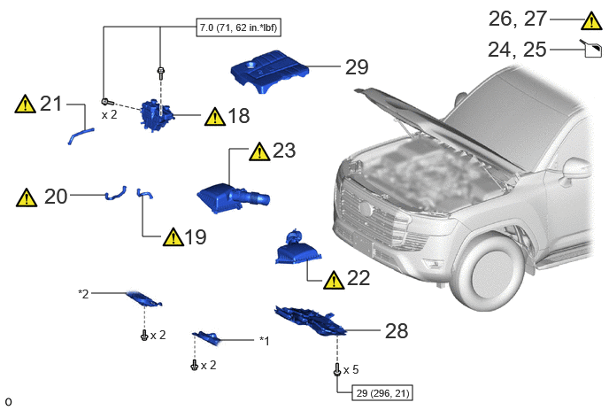
18 RADIATOR RESERVE TANK ASSEMBLY 164A2 (Click here) - -
19 NO. 2 WATER BY-PASS HOSE 16264D (Click here) - -
20 WATER BY-PASS HOSE ASSEMBLY 16260 (Click here) - -
21 WATER BY-PASS HOSE 16261 (Click here) - -
22 AIR CLEANER CAP WITH AIR CLEANER HOSE ASSEMBLY LH 17735 (Click here) - -
23 AIR CLEANER CAP WITH AIR CLEANER HOSE ASSEMBLY RH 17735 (Click here) - -
24 ADD ENGINE COOLANT - - (Click here) -
25 ADD COOLANT (for Intercooler) - - (Click here) -
26 INSPECT FOR COOLANT LEAK - (Click here) - -
27 INSPECT FOR COOLANT LEAK (for Intercooler) - (Click here) - -
28 NO. 1 ENGINE UNDER COVER ASSEMBLY 51410 - - -
29 V-BANK COVER SUB-ASSEMBLY 11209 - - -

*1 ENGINE SIDE COVER SUB-ASSEMBLY LH *2 ENGINE SIDE COVER SUB-ASSEMBLY RH
V100146

N*m (kgf*cm, ft.*lbf): Specified torque - -

PROCEDURE

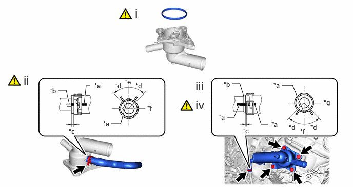
Hide 16031 1.INSTALL WATER INLET SUB-ASSEMBLY WITH THERMOSTAT

a.
A535875C02
1.708,2.104 1.75,1.75 1.75,1.75 1.833,1.75 true 2.594,2.021 2.448,2.521 2.448,2.521 2.26,2.521 true 1.406,2.115 1.344,1.844 1.344,1.844 1.177,1.844 true 4.719,1.698 4.865,1.698 4.865,1.698 4.948,1.958 false 6.167,2.281 5.938,1.74 5.938,1.74 5.729,1.74 true 5.177,2.146 5.302,2.531 5.302,2.531 5.438,2.531 true 4.615,2.396 4.75,2.396 4.75,2.396 4.854,2.146 true 0.479,1.49 0.698,1.771 0.219,0.281 18 false ii 2.74,0.125 2.979,0.406 0.24,0.281 18 false i 1.396,2.594 1.646,2.802 0.25,0.208 10 false *c 2.75,1.667 3,1.875 0.25,0.208 10 false *d 1.917,1.667 2.167,1.875 0.25,0.208 10 false *a 5.51,2.448 5.76,2.656 0.25,0.208 10 false *a 4.927,2.583 5.177,2.792 0.25,0.208 10 false *c 6.302,2.51 6.552,2.719 0.25,0.208 10 false *d 1.01,1.771 1.26,1.979 0.25,0.208 10 false *b 4.542,1.635 4.792,1.844 0.25,0.208 10 false *b 2.99,2.125 3.24,2.333 0.25,0.208 10 false *f 2.531,1.583 2.781,1.792 0.25,0.208 10 false *e 6.573,2 6.823,2.208 0.25,0.208 10 false *g 6.094,2.604 6.344,2.813 0.25,0.208 10 false *f 3.969,1.604 4.188,1.885 0.219,0.281 18 false iii 3.969,1.99 4.188,2.271 0.219,0.281 18 false iv 4.438,2.302 4.688,2.51 0.25,0.208 10 false *a 5.865,2.51 6.115,2.719 0.25,0.208 10 false *d 5.552,1.656 5.802,1.865 0.25,0.208 10 false *a 2.333,1.667 2.583,1.875 0.25,0.208 10 false *d 2.094,2.438 2.344,2.646 0.25,0.208 10 false *a
*a Paint Mark *b Stopper
*c 1.0 to 7.0 mm (0.0394 to 0.276 in.) *d 45°
*e Upper Side *f Front Side
*g LH Side - -


i.

Install a new gasket to the thermostat.


ii.

Connect the No. 4 water by-pass hose to the water inlet sub-assembly with thermostat and slide the hose clip to secure it as shown in the illustration.

NOTICE:
·

Install so that the paint mark and positioning stopper are securely overlapped.

·

Make sure the No. 4 water by-pass hose is securely inserted to the stopper.


iii.

Install the water inlet sub-assembly with thermostat to the cylinder block assembly with the 4 bolts.

Torque:
25 N*m (255 kgf*cm, 18 ft.*lbf)


iv.

Connect the No. 4 water by-pass hose to the No. 1 water by-pass pipe assembly and slide the hose clip to secure it as shown in the illustration.

NOTICE:
·

Install so that the paint mark and the paint mark on the pipe are securely overlapped.

·

Make sure the No. 4 water by-pass hose is securely inserted to the stopper.


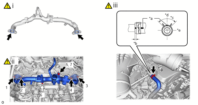
Hide 2.INSTALL WATER OUTLET PIPE WITH WATER BY-PASS JOINT

a.
A487181C01
5.583,0.667 5.75,0.667 5.75,0.667 6.021,0.896 true 5.167,1 5.167,0.667 5.167,0.667 5.333,0.667 true 0.438,0.052 0.688,0.333 0.25,0.281 18 false i 0.417,2.073 0.667,2.354 0.25,0.281 18 true ii 0.198,3.094 0.354,3.26 0.156,0.167 10 true 1 0.74,3.188 0.906,3.365 0.167,0.177 10 true 2 3.104,3.031 3.271,3.208 0.167,0.177 10 true 3 2.531,3.188 2.677,3.365 0.146,0.177 10 true 4 2.385,2.26 2.656,2.448 0.271,0.188 10 true 5, 7 1.448,3.365 1.615,3.542 0.167,0.177 10 true 6 5.396,0.583 5.604,0.802 0.208,0.219 10 false *a 4.833,1.49 5.042,1.708 0.208,0.219 10 false *b 6.167,0.552 6.375,0.771 0.208,0.219 10 false *c 6.406,1.01 6.615,1.229 0.208,0.219 10 false *e 5.969,0.458 6.177,0.677 0.208,0.219 10 false *d 4.094,0.031 4.344,0.313 0.25,0.281 18 false iii
*a Paint Mark *b 1.0 to 7.0 mm (0.0394 to 0.276 in.)
*c 90° *d Upper Side
*e LH Side - -
V100135

Bolt A
V100136

Bolt B


i.

Install 2 new gaskets to the water outlet pipe with water by-pass joint.


ii.

Tighten the 6 bolts in the order shown in the illustration.

Torque:
21 N*m (214 kgf*cm, 15 ft.*lbf)


iii.

Connect the No. 9 water by-pass hose to the water outlet pipe with water by-pass joint and slide the clip to secure it as shown in the illustration.


Hide 44310 3.CONNECT VANE PUMP ASSEMBLY

Z101186

Click here(Click here)

Hide 88310A 4.INSTALL NO. 1 V BELT (COOLER COMPRESSOR TO CRANKSHAFT PULLEY)

Z101186

Click here(Click here)

Hide 1629A 5.CONNECT NO. 14 WATER BY-PASS HOSE
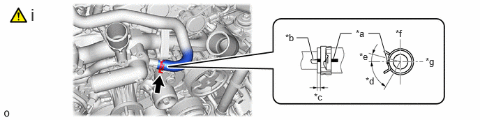
a.
A487179C01
4.979,0.875 5.083,0.5 5.083,0.5 5.25,0.5 true 4.677,0.896 4.594,0.563 4.594,0.563 4.427,0.563 true 5.781,0.906 5.667,0.5 5.667,0.5 5.5,0.5 true 0.458,0.073 0.688,0.344 0.229,0.271 18 false i 4.688,1.365 4.885,1.563 0.198,0.198 10 false *c 5.365,0.76 5.563,0.958 0.198,0.198 10 false *e 5.458,1.125 5.656,1.323 0.198,0.198 10 false *d 6.354,0.833 6.552,1.031 0.198,0.198 10 false *g 5.906,0.417 6.104,0.615 0.198,0.198 10 false *f 5.313,0.417 5.51,0.615 0.198,0.198 10 false *a 4.26,0.479 4.458,0.677 0.198,0.198 10 false *b
*a Paint Mark *b Stopper
*c 1.0 to 7.0 mm (0.0394 to 0.276 in.) *d 60°
*e 15° *f Upper Side
*g Rear Side - -


i.

Connect the No. 14 water by-pass hose to the water inlet sub-assembly with thermostat and slide the clip to secure it as shown in the illustration.

NOTICE:
·

Install so that the paint mark and positioning stopper are securely overlapped.

·

Make sure the No. 14 water by-pass hose is securely inserted to the stopper.


Hide 16282 6.CONNECT NO. 5 WATER BY-PASS HOSE
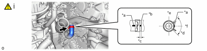
a.
A487177C02
4.896,0.719 4.958,0.49 4.958,0.49 5.104,0.49 true 4.625,0.875 4.542,0.542 4.542,0.542 4.375,0.542 true 6.042,0.885 6.156,0.427 6.156,0.427 6.344,0.427 true 0.458,0.063 0.677,0.313 0.219,0.25 18 false i 4.781,1.354 4.979,1.552 0.198,0.198 10 false *c 5.792,0.365 5.99,0.563 0.198,0.198 10 false *e 6.406,0.833 6.604,1.031 0.198,0.198 10 false *f 5.146,0.406 5.344,0.604 0.198,0.198 10 false *b 4.219,0.448 4.417,0.646 0.198,0.198 10 false *a 6.375,0.344 6.573,0.542 0.198,0.198 10 false *a 6.26,1.073 6.458,1.271 0.198,0.198 10 false *d
*a Paint Mark *b Stopper
*c 1.0 to 7.0 mm (0.0394 to 0.276 in.) *d 90°
*e Front Side *f RH Side


i.

Connect the No. 5 water by-pass hose to the water outlet pipe with water by-pass joint and slide the clip to secure it as shown in the illustration.

NOTICE:
·

Install so that the paint mark and the paint mark on the pipe are securely overlapped.

·

Make sure the No. 5 water by-pass hose is securely inserted to the stopper.


Hide 16261Q 7.CONNECT WATER BY-PASS HOSE

a.
A487175C02
4.896,0.708 4.958,0.448 4.958,0.448 5.146,0.448 true 4.625,0.875 4.542,0.542 4.542,0.542 4.375,0.542 true 6.042,0.885 6.156,0.427 6.156,0.427 6.344,0.427 true 0.458,0.063 0.677,0.313 0.219,0.25 18 false i 4.781,1.354 4.979,1.552 0.198,0.198 10 false *c 5.771,0.385 5.969,0.583 0.198,0.198 10 false *e 6.406,0.833 6.604,1.031 0.198,0.198 10 false *f 5.167,0.375 5.365,0.573 0.198,0.198 10 false *b 4.219,0.448 4.417,0.646 0.198,0.198 10 false *a 6.375,0.344 6.573,0.542 0.198,0.198 10 false *a 6.26,1.073 6.458,1.271 0.198,0.198 10 false *d
*a Paint Mark *b Stopper
*c 1.0 to 7.0 mm (0.0394 to 0.276 in.) *d 90°
*e Upper Side *f LH Side


i.

Connect the water by-pass hose to the water outlet pipe with water by-pass joint and slide the clip to secure it as shown in the illustration.

NOTICE:
·

Install so that the paint mark and the paint mark on the pipe are securely overlapped.

·

Make sure the water by-pass hose is securely inserted to the stopper.


Hide 8.INSTALL WATER INLET PIPE WITH WATER BY-PASS HOSE
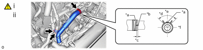
a.
A487173C02
4.885,0.875 4.99,0.5 4.99,0.5 5.156,0.5 true 4.823,0.885 4.74,0.552 4.74,0.552 4.573,0.552 true 5.927,0.781 6.24,0.448 6.24,0.448 6.375,0.448 true 0.469,0.052 0.688,0.302 0.219,0.25 18 false i 4.771,1.354 4.969,1.552 0.198,0.198 10 false *c 5.823,0.323 6.021,0.521 0.198,0.198 10 false *e 5.615,0.406 5.813,0.604 0.198,0.198 10 false *d 6.292,0.896 6.49,1.094 0.198,0.198 10 false *f 5.177,0.417 5.375,0.615 0.198,0.198 10 false *b 4.427,0.448 4.625,0.646 0.198,0.198 10 false *a 6.417,0.344 6.615,0.542 0.198,0.198 10 false *a 0.458,0.375 0.677,0.625 0.219,0.25 18 false ii
*a Paint Mark *b Stopper
*c 1.0 to 7.0 mm (0.0394 to 0.276 in.) *d 90°
*e Upper Side *f Front Side


i.

Connect the water inlet pipe with water by-pass hose to the water inlet sub-assembly with thermostat and slide the clip to secure it as shown in the illustration.

NOTICE:
·

Install so that the paint mark and positioning stopper are securely overlapped.

·

Make sure the water by-pass hose is securely inserted to the stopper.


ii.

Install the water inlet pipe with water by-pass hose to the alternator bracket sub-assembly with the 2 bolts.

Torque:
21 N*m (214 kgf*cm, 15 ft.*lbf)


Hide 16267C 9.CONNECT NO. 4 WATER BY-PASS HOSE
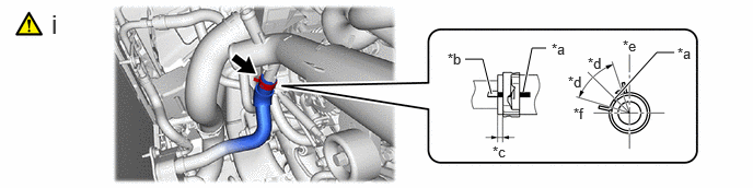
a.
A535876C02
4.979,0.875 5.063,0.458 5.063,0.458 5.198,0.458 true 4.677,0.896 4.594,0.563 4.594,0.563 4.427,0.563 true 5.854,0.938 6.25,0.5 6.25,0.5 6.417,0.5 true 0.49,0.083 0.708,0.333 0.219,0.25 18 false i 4.688,1.365 4.885,1.563 0.198,0.198 10 false *c 5.594,0.521 5.792,0.719 0.198,0.198 10 false *d 5.458,1 5.656,1.198 0.198,0.198 10 false *f 5.927,0.354 6.125,0.552 0.198,0.198 10 false *e 5.25,0.385 5.448,0.583 0.198,0.198 10 false *a 4.26,0.479 4.458,0.677 0.198,0.198 10 false *b 6.448,0.427 6.646,0.625 0.198,0.198 10 false *a 5.406,0.698 5.604,0.896 0.198,0.198 10 false *d
*a Paint Mark *b Stopper
*c 2.0 to 5.0 mm (0.0787 to 0.197 in.) *d 25°
*e Front Side *f RH Side


i.

Connect the No. 4 water by-pass hose to the water inlet pipe and slide the clip to secure it as shown in the illustration.

NOTICE:
·

Install so that the paint mark and positioning stopper are securely overlapped.

·

Make sure the No. 4 water by-pass hose is securely inserted to the stopper.


Hide 17343N 10.INSTALL NO. 3 AIR HOSE

Z101186

Click here(Click here)

Hide 17341M 11.INSTALL NO. 1 AIR HOSE

Z101186

Click here(Click here)

Hide 12.INSTALL NO. 2 AIR TUBE ASSEMBLY

Z101186

Click here(Click here)

Hide 13.INSTALL NO. 1 AIR TUBE ASSEMBLY

Z101186

Click here(Click here)

Hide 16364A 14.INSTALL COOLING FAN WIRE

Z101186

Click here(Click here)

Hide 16572D 15.CONNECT NO. 2 RADIATOR HOSE

Z101186

Click here(Click here)

Hide 16571C 16.INSTALL NO. 1 RADIATOR HOSE

Z101186

Click here(Click here)

Hide 82121 17.CONNECT ENGINE WIRE

Torque:
10 N*m (102 kgf*cm, 7 ft.*lbf)

Hide 164A2 18.INSTALL RADIATOR RESERVE TANK ASSEMBLY

Z101186

Click here(Click here)

Hide 16264D 19.CONNECT NO. 2 WATER BY-PASS HOSE

Z101186

Click here(Click here)

Hide 16260 20.CONNECT WATER BY-PASS HOSE ASSEMBLY

Z101186

Click here(Click here)

Hide 16261 21.CONNECT WATER BY-PASS HOSE

Z101186

Click here(Click here)

Hide 17735 22.INSTALL AIR CLEANER CAP WITH AIR CLEANER HOSE ASSEMBLY LH

Z101186

Click here(Click here)

Hide 17735 23.INSTALL AIR CLEANER CAP WITH AIR CLEANER HOSE ASSEMBLY RH

Z101186

Click here(Click here)

Hide 24.ADD ENGINE COOLANT

Hide 25.ADD COOLANT (for Intercooler)

Hide 27.INSPECT FOR COOLANT LEAK (for Intercooler)

Hide 51410 28.INSTALL NO. 1 ENGINE UNDER COVER ASSEMBLY

Hide 11209 29.INSTALL V-BANK COVER SUB-ASSEMBLY