SEAT SEAT HEATER SYSTEM Seat Heater for Rear Right Seat does not Operate
DESCRIPTION
When the seat heater switch (rear right) is operated, the air conditioning amplifier assembly receives the signal from the cooler control assembly via the LIN communication line and operates the rear right side seat heater.
WIRING DIAGRAM
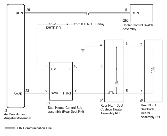
CAUTION / NOTICE / HINT
- NOTICE:
-
·
If the battery voltage is low, the seat heater system may not operate. When "High Power Consumption Partial Limit on AC/Heater Operation" is displayed on the multi-information display in the combination meter assembly, inspect the battery, referring to On-vehicle Inspection for the charging system.
for 1GR-FE: Click herePower Source / Network>1GR-FE (BATTERY / CHARGING)>CHARGING SYSTEM>ON-VEHICLE INSPECTION
for V35A-FTS: Click herePower Source / Network>V35A-FTS (BATTERY / CHARGING)>CHARGING SYSTEM>ON-VEHICLE INSPECTION
for F33A-FTV: Click herePower Source / Network>F33A-FTV (BATTERY / CHARGING)>CHARGING SYSTEM>ON-VEHICLE INSPECTION
·w/ Power Tilt and Power Telescopic Steering Column
If the mirror heater is operated when the battery voltage is low, due to the electrical load limit control that gives voltage supply priority to the power steering system, the mirror heater may not operate. In this case, check the vehicle control history of the power steering system and check that "Battery Voltage Drop: X21B6" is not stored before proceeding with troubleshooting.
·Inspect the fuses for circuits related to this system before performing the following procedure.
PROCEDURE
Perform the Active Test according to the display on the GTS.
- Body Electrical > Air Conditioner > Active Test
-
Tester Display Measurement Item Control Range Diagnostic Note Rear Right Seat Heater RH side rear seat heater operation OFF/ON -
- Body Electrical > Air Conditioner > Active Test
-
Tester Display Rear Right Seat Heater - 50004 121 118
- OK:
-
Rear right side seat heater operates normally.
- Result:
-
Proceed to OK NG
OK
NG
Replace the air conditioner amplifier assembly with a new one or known good one.
Click hereVehicle Interior>HEATING / AIR CONDITIONING>AIR CONDITIONING AMPLIFIER>REMOVAL
- Result:
-
Proceed to NEXT
NEXT
Check the rear right side seat heater operation.
Click hereVehicle Interior>SEAT>SEAT HEATER SYSTEM>OPERATION CHECK
- OK:
-
Rear right side seat heater operates normally.
- Result:
-
Proceed to OK NG
OK
NG
Disconnect the j1 seat heater control sub-assembly (rear seat RH) connector.
Measure the voltage according to the value(s) in the table below.
- Standard Voltage:
-
Tester Connection Switch Condition Specified Condition Click Location & Routing(j1)Location & Routingewd_type=routing;type=c;code=j1
Click Connector(j1)Seat>Rear Seat Wire RH>Seat Heater Control Sub-Assembly RH (Rear Seat RH)ewd_type=component;type=c;code=j1;pinno=1
j1-1 (+B1) - Body ground Ignition switch ON 11 to 14 V j1-1 (+B1) - Body ground Ignition switch off Below 1 V
- Result:
-
Proceed to OK NG
OK
NG
Disconnect the I31 air conditioning amplifier assembly connector.
Disconnect the j1 seat heater control sub-assembly (rear seat RH) connector.
Measure the resistance according to the value(s) in the table below.
- Standard Resistance:
-
Tester Connection Condition Specified Condition Click Location & Routing(I31,j1)Location & Routingewd_type=routing;type=c,c;code=I31,j1
Click Connector(j1)Seat>Rear Seat Wire RH>Seat Heater Control Sub-Assembly RH (Rear Seat RH)ewd_type=component;type=c;code=j1;pinno=5
I31-23 (SM2R) - j1-5 (SWR) Always Below 1 Ω I31-23 (SM2R) or j1-5 (SWR) - Body ground Always 10 kΩ or higher
- Result:
-
Proceed to OK NG
OK
NG
Disconnect the j2 rear No. 1 seat cushion heater assembly RH connector.
Disconnect the j1 seat heater control sub-assembly (rear seat RH) connector.
Measure the resistance according to the value(s) in the table below.
- Standard Resistance:
-
Tester Connection Condition Specified Condition Click Location & Routing(j2,j1)Location & Routingewd_type=routing;type=c,c;code=j2,j1
Click Connector(j2)Seat>Rear Seat Wire RH>Rear Seat Cushion Heater RH (Rear No. 1 Seat Cushion Pad RH)ewd_type=component;type=c;code=j2;pinno=3,1
Click Connector(j1)Seat>Rear Seat Wire RH>Seat Heater Control Sub-Assembly RH (Rear Seat RH)ewd_type=component;type=c;code=j1;pinno=10,7
j2-3 - j1-10(E) Always Below 1 Ω j2-1 - j1-7(HTR) Always Below 1 Ω j2-3 or j1-10 (E) - Body ground Always 10 kΩ or higher j2-1 or j1-7(HTR) - Body ground Always 10 kΩ or higher
- Result:
-
Proceed to OK NG
OK
NG
Disconnect the j2 rear No. 1 seat cushion heater assembly RH connector.
Disconnect the j8 rear No. 1 seatback heater assembly RH connector.
Measure the resistance according to the value(s) in the table below.
- Standard Resistance:
-
Tester Connection Condition Specified Condition Click Location & Routing(j2,j8)Location & Routingewd_type=routing;type=c,c;code=j2,j8
Click Connector(j2)Seat>Rear Seat Wire RH>Rear Seat Cushion Heater RH (Rear No. 1 Seat Cushion Pad RH)ewd_type=component;type=c;code=j2;pinno=5,8
Click Connector(j8)Seat>Rear Seat Wire RH>Rear Seat Back Heater RH (No. 1 Seat Back Pad RH)ewd_type=component;type=c;code=j8;pinno=1,2
j2-5 - j8-1 Always Below 1 Ω j2-5 or j8-1 - Other terminals Always 10 kΩ or higher j2-8 - j8-2 Always Below 1 Ω j2-8 or j8-2 - Other terminals Always 10 kΩ or higher
- Result:
-
Proceed to OK NG
OK
NG
Click hereVehicle Interior>SEAT>REAR SEATBACK HEATER (for 40/20/40 Split Seat Type RH Side)>INSPECTION
- Result:
-
Proceed to OK NG
OK
NG
Click hereVehicle Interior>SEAT>REAR SEAT CUSHION HEATER (for 40/20/40 Split Seat Type RH Side)>INSPECTION
- Result:
-
Proceed to OK NG
OK
NG
Click hereVehicle Interior>SEAT>REAR SEAT CUSHION HEATER (for 40/20/40 Split Seat Type RH Side)>REMOVAL
Replace the seat heater control sub-assembly (rear seat RH) with a new one or known good one.
Click hereVehicle Interior>SEAT>SEAT HEATER CONTROL (for 40/20/40 Split Seat Type RH Side)>REMOVAL
- Result:
-
Proceed to NEXT
NEXT
Check the rear right side seat heater operation.
Click hereVehicle Interior>SEAT>SEAT HEATER SYSTEM>OPERATION CHECK
- OK:
-
Rear right side seat heater operates normally.
- Result:
-
Proceed to OK NG
OK
NG