F33A-FTV INTAKE / EXHAUST TURBOCHARGER INSTALLATION
CAUTION / NOTICE / HINT
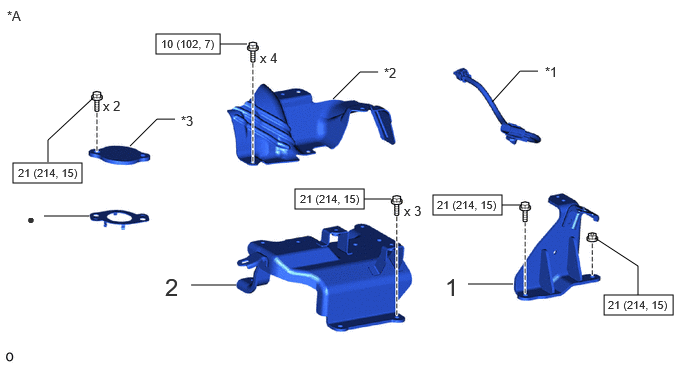
| Procedure | Part Name Code |

|

|

|
|
|---|---|---|---|---|---|
| 1 | NO. 2 CLAMP STAY | 17561H | - | - | - |
| 2 | CLAMP STAY | 17561G | - | - | - |
| *A | w/o EGR System | - | - |
| *1 | CONNECTING WIRE | *2 | EGR COOLER INSULATOR |
| *3 | EGR HOLE COVER PLATE | - | - |

|
N*m (kgf*cm, ft.*lbf): Specified torque | ● | Non-reusable part |
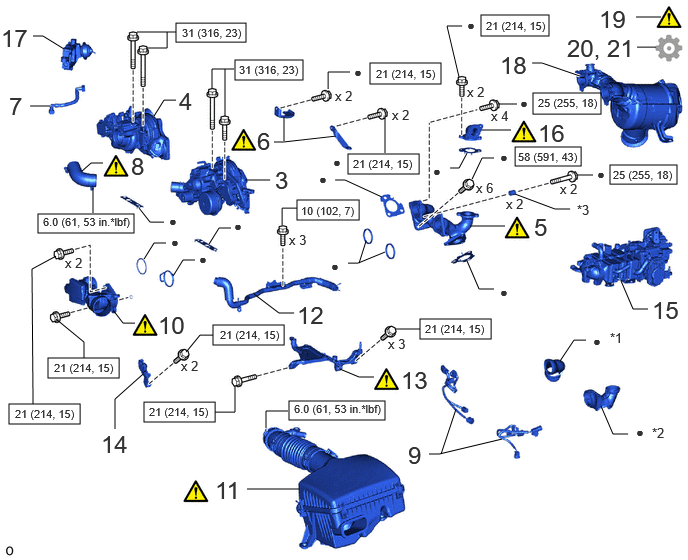
| Procedure | Part Name Code |
|
|
|
|
|---|---|---|---|---|---|
| 3 | NO. 2 TURBOCHARGER SUB-ASSEMBLY | 17208 | - | - | - |
| 4 | TURBOCHARGER SUB-ASSEMBLY | 17201 | - | - | - |
| 5 | EXHAUST CROSSOVER PIPE SUB-ASSEMBLY | 17106 | - | ( ) |
- |
| 6 | TURBOCHARGER BRACKET | - | () |
- | - |
| 7 | FUEL TUBE SUB-ASSEMBLY | 23901H | - | - | - |
| 8 | AIR HOSE | 17341H | () |
- | - |
| 9 | TURBOCHARGER WIRE | 1723A | - | - | - |
| 10 | COMPRESSOR INLET ELBOW | 17274 | () |
- | - |
| 11 | AIR CLEANER ASSEMBLY WITH AIR CLEANER HOSE | 17700 | () |
- | - |
| 12 | VENTILATION PIPE | 12229 | - | - | - |
| 13 | NO. 1 EGR COOLER BRACKET | 25687 | () |
- | - |
| 14 | FUEL SUPPORT | 23849 | - | - | - |
| 15 | EGR COOLER WITH ELECTRIC EGR CONTROL VALVE ASSEMBLY | - | - | - | - |
| 16 | EGR INLET | 25618 | () |
- | - |
| 17 | INTAKE AIR CONTROL VALVE ASSEMBLY | 17300 | - | - | - |
| 18 | EXHAUST MANIFOLD CONVERTER SUB-ASSEMBLY | 25051 | - | - | - |
| 19 | INSPECT FOR EXHAUST GAS LEAK | - | () |
- | - |
| 20 | PERFORM REGISTRATION | - | - | - | () |
| 21 | PERFORM INITIALIZATION | - | - | - | () |
| *1 | NO. 1 EXHAUST MANIFOLD HEAT INSULATOR | *2 | NO. 2 EXHAUST MANIFOLD HEAT INSULATOR |
| *3 | COLLAR | - | - |
|
|
N*m (kgf*cm, ft.*lbf): Specified torque | ● | Non-reusable part |
PROCEDURE

 17561H 1.INSTALL NO. 2 CLAMP STAY (w/o EGR System)
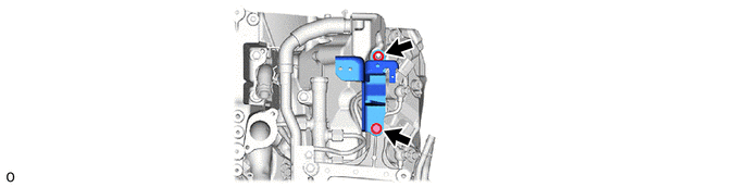
- Torque:
- 21 N・m (214 kgf・cm, )
17561G 2.INSTALL CLAMP STAY (w/o EGR System)
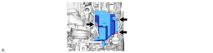
- Torque:
- 21 N・m (214 kgf・cm, )
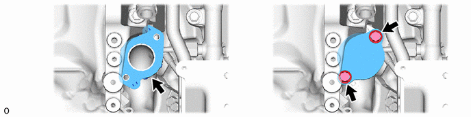
- Torque:
- 21 N・m (214 kgf・cm, )
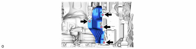
- Torque:
- 10 N・m (102 kgf・cm, )
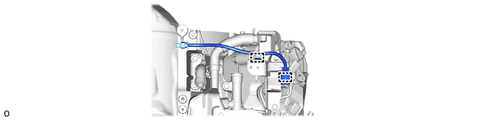
17208 3.INSTALL NO. 2 TURBOCHARGER SUB-ASSEMBLY
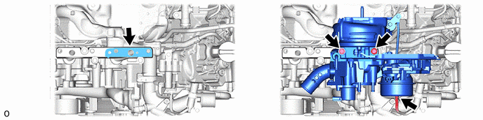
- Torque:
- 31 N*m (316 kgf*cm, 23 ft.*lbf)
17201 4.INSTALL TURBOCHARGER SUB-ASSEMBLY
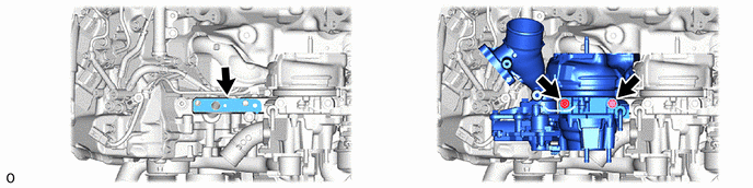
- Torque:
- 31 N*m (316 kgf*cm, 23 ft.*lbf)
17106 5.INSTALL EXHAUST CROSSOVER PIPE SUB-ASSEMBLY
|
|
|
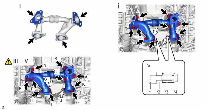
| *1 | Turbocharger Sub-assembly | *2 | Exhaust Crossover Pipe Sub-assembly |
| *3 | Collar | *4 | Bolt |
| *a | Collar Orientation | - | - |

|
Bolt |

|
Bolt and Collar |
Install the 4 new gaskets to the exhaust crossover pipe sub-assembly.
Temporarily install the exhaust crossover pipe sub-assembly and No. 1 exhaust manifold heat insulator, No. 2 exhaust manifold heat insulator with the 2 collars and 12 new bolts.
- NOTICE:
-
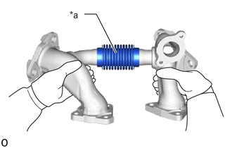 1.25,0.208 1.427,0.208 1.427,0.208 1.719,0.781 true 1.031,0.135 1.281,0.313 0.25,0.177 10 false *a
*a Bellows
-
Hold the bellows with both hands in parallel to avoid damaging the inside of the bellows.
Temporarily install the 6 bolts from bolt A to bolt F on the cylinder head sub-assembly side as shown in the illustration.
- Torque:
- 5.0 N*m (51 kgf*cm, 44 in.*lbf)
- HINT:
-
Temporarily install order: Temporarily install bolt (A) → Temporarily install bolt (B) → Temporarily install bolt (C) → Temporarily install bolt (D) → Temporarily install bolt (E) → Temporarily install bolt (F)
Tighten the 6 bolts from bolt G to bolt L on the turbocharger sub-assembly side as shown in the illustration.
- Torque:
- 25 N*m (255 kgf*cm, 18 ft.*lbf)
- HINT:
-
Tightening order: Tighten bolt (G) → Tighten bolt (H) → Tighten bolt (I) → Tighten bolt (J) → Tighten bolt (K) → Tighten bolt (L)
Tighten the 6 bolts from bolt A to bolt F on the cylinder head sub-assembly side as shown in the illustration.
- Torque:
- 58 N*m (591 kgf*cm, 43 ft.*lbf)
- HINT:
-
Tightening order: Tighten bolt (A) → Tighten bolt (B) → Tighten bolt (C) → Tighten bolt (D) → Tighten bolt (E) → Tighten bolt (F)
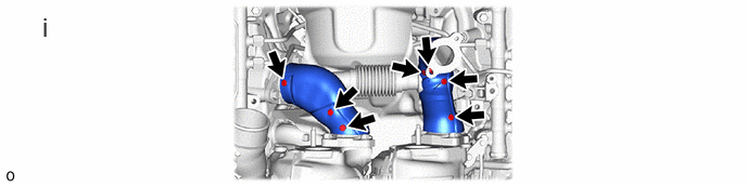
Attach the 7 snap fasteners and connect the No. 1 exhaust manifold heat insulator and No. 2 exhaust manifold heat insulator.
6.INSTALL TURBOCHARGER BRACKET
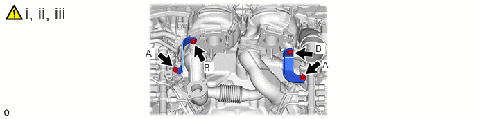
Temporarily install the turbocharger bracket with 2 new bolts (A).
Install 2 new bolts (B).
- Torque:
- 21 N*m (214 kgf*cm, 15 ft.*lbf)
Tighten 2 new bolts (A).
- Torque:
- 21 N*m (214 kgf*cm, 15 ft.*lbf)
23901H 7.INSTALL FUEL TUBE SUB-ASSEMBLY
17341H 8.INSTALL AIR HOSE
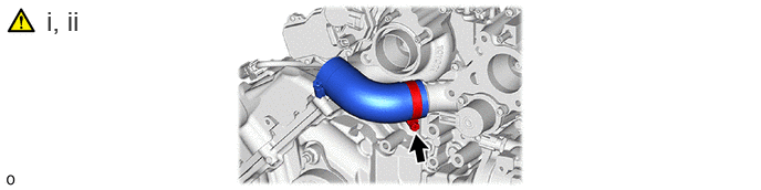
Install the hose clamp to the air hose.
- NOTICE:
-
Thoroughly degrease the air hose and the points where it connects to the vehicle before installation.
Install the air hose and tighten the hose clamp.
- Torque:
- 6.0 N*m (61 kgf*cm, 53 in.*lbf)
1723A 9.INSTALL TURBOCHARGER WIRE
17274 10.INSTALL COMPRESSOR INLET ELBOW
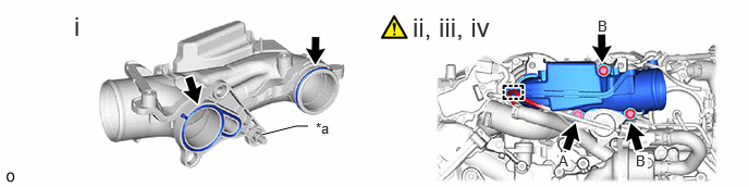
| *a | Bolt Fall Prevention O-Ring | - | - |
Install the 2 new gaskets to the compressor inlet elbow as shown in the illustration.
Temporarily install the compressor inlet elbow with the bolt (A).
- NOTICE:
-
Bolt A has a fall prevention O-ring.
Temporarily install the 2 bolts (B).
Tighten the bolt (A) and 2 bolts (B).
- Torque:
- 21 N*m (214 kgf*cm, 15 ft.*lbf)
Connect the turbocharger wire.
17700 11.INSTALL AIR CLEANER ASSEMBLY WITH AIR CLEANER HOSE
|
|
() |
12229 12.INSTALL VENTILATION PIPE
- Torque:
- 10 N*m (102 kgf*cm, 7 ft.*lbf)
25687 13.INSTALL NO. 1 EGR COOLER BRACKET
|
|
() |
23849 14.INSTALL FUEL SUPPORT
- Torque:
- 21 N*m (214 kgf*cm, 15 ft.*lbf)
15.INSTALL EGR COOLER WITH ELECTRIC EGR CONTROL VALVE ASSEMBLY
25618 16.INSTALL EGR INLET
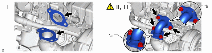
| *a | ●Mark | *b | ▲Mark |
Install the 2 new gaskets to the exhaust crossover pipe sub-assembly and EGR valve adapter as shown in the illustration.
Temporarily install the EGR inelt with the 4 new bolts as shown in the illustration.
Tighten the 4 bolts.
- Torque:
- 21 N*m (214 kgf*cm, 15 ft.*lbf)
17300 17.INSTALL INTAKE AIR CONTROL VALVE ASSEMBLY
25051 18.INSTALL EXHAUST MANIFOLD CONVERTER SUB-ASSEMBLY
19.INSPECT FOR EXHAUST GAS LEAK
20.PERFORM REGISTRATION
Perform registration of turbocharger compensation codes.
21.PERFORM INITIALIZATION
Perform "Inspection After Repair" after replacing the turbocharger sub-assembly.