F33A-FTV ENGINE CONTROL DIESEL THROTTLE BODY INSTALLATION
CAUTION / NOTICE / HINT
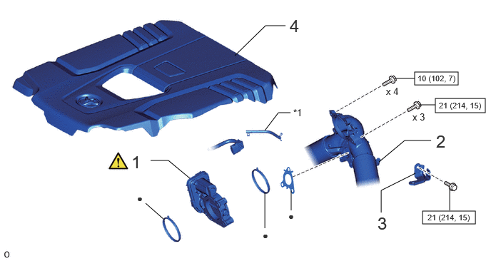
| Procedure | Part Name Code |

|

|

|
|
|---|---|---|---|---|---|
| 1 | DIESEL THROTTLE BODY ASSEMBLY | 26100G | ( ) |
- | - |
| 2 | NO. 1 INTAKE PIPE | 17113E | - | - | - |
| 3 | INTAKE PIPE OR HOSE STAY | 17138 | - | - | - |
| 4 | NO. 1 ENGINE COVER SUB-ASSEMBLY | 12601B | - | - | - |
| *1 | Vacuum Hose | - | - |

|
N*m (kgf*cm, ft.*lbf): Specified torque | ● | Non-reusable part |
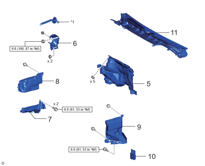
| Procedure | Part Name Code |
|
|
|
|
|---|---|---|---|---|---|
| 5 | DASH PANEL INSULATOR OUTER | 55223A | - | - | - |
| 6 | NO. 1 HEATER COVER | 87114E | - | - | - |
| 7 | REAR ENGINE SIDE UNDER COVER ASSEMBLY RH | 51460C | - | - | - |
| 8 | ENGINE SIDE UNDER COVER RH | 51448M | - | - | - |
| 9 | REAR ENGINE SIDE UNDER COVER ASSEMBLY LH | 51470C | - | - | - |
| 10 | UPPER ENGINE SIDE UNDER COVER PLATE LH | 51478C | - | - | - |
| 11 | COWL TOP VENTILATOR LOUVER SUB-ASSEMBLY | 55708 | - | - | - |
| *1 | Outlet Heater Water Hose A | - | - |
|
|
N*m (kgf*cm, ft.*lbf): Specified torque | - | - |
PROCEDURE

 26100G 1.INSTALL DIESEL THROTTLE BODY ASSEMBLY
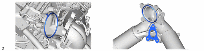
Install new gaskets.
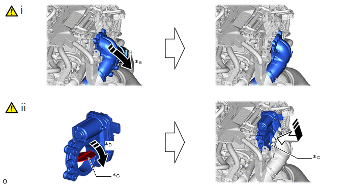
| *a | Push toward rear | *b | Close throttle valve |
| *c | Throttle valve | - | - |
Push the No. 1 intake pipe toward the rear to secure space.
Set the diesel throttle body assembly with the throttle valve closed.

Connect the connector.
17113E 2.INSTALL NO. 1 INTAKE PIPE

Connect the intake pipe to EGR pipe with 3 bolts.
- Torque:
- 21 N*m (214 kgf*cm, 15 ft.*lbf)
Connect the intake pipe to diesel throttle body with 4 bolts.
- Torque:
- 10 N*m (102 kgf*cm, 7 ft.*lbf)

Connect the vacuum hose and secure it with the clip.
17138 3.INSTALL INTAKE PIPE OR HOSE STAY

Install the hose stay with the bolt.
- Torque:
- 21 N*m (214 kgf*cm, 15 ft.*lbf)
12601B 4.INSTALL NO. 1 ENGINE COVER SUB-ASSEMBLY
55223A 5.INSTALL DASH PANEL INSULATOR OUTER
87114E 6.INSTALL NO. 1 HEATER COVER
51460C 7.INSTALL REAR ENGINE SIDE UNDER COVER ASSEMBLY RH
51448M 8.INSTALL ENGINE SIDE UNDER COVER RH
51470C 9.INSTALL REAR ENGINE SIDE UNDER COVER ASSEMBLY LH
51478C 10.INSTALL UPPER ENGINE SIDE UNDER COVER PLATE LH
55708 11.INSTALL COWL TOP VENTILATOR LOUVER SUB-ASSEMBLY
12.PERFORM INITIALIZATION
13.INSPECT OPERATION