HEATING / AIR CONDITIONING FRONT AIR CONDITIONING UNIT(for LHD) INSTALLATION
CAUTION / NOTICE / HINT
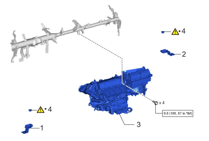
| Procedure | Part Name Code |

|

|

|
|
|---|---|---|---|---|---|
| 1 | NO. 1 COOLING UNIT BRACKET | 88536 | - | - | - |
| 2 | NO. 2 COOLING UNIT BRACKET | 88536A | - | - | - |
| 3 | AIR CONDITIONER UNIT ASSEMBLY | - | - | - | - |
| 4 | COOLER UNIT DRAIN HOSE GROMMET | 88539G | ( ) |
- | - |

|
N*m (kgf*cm, ft.*lbf): Specified torque | ● | Non-reusable part |
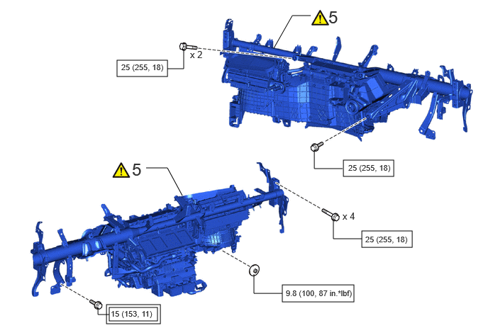
| Procedure | Part Name Code |
|
|
|
|
|---|---|---|---|---|---|
| 5 | INSTRUMENT PANEL REINFORCEMENT ASSEMBLY WITH AIR CONDITIONING UNIT ASSEMBLY | - | () |
- | - |

|
Tightening torque for "Major areas involving basic vehicle performance such as moving/turning/stopping": N*m (kgf*cm, ft.*lbf) |
|
N*m (kgf*cm, ft.*lbf): Specified torque |
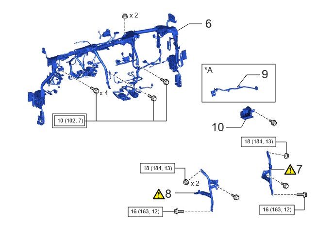
| Procedure | Part Name Code |
|
|
|
|
|---|---|---|---|---|---|
| 6 | INSTRUMENT PANEL WIRE | 82141 | - | - | - |
| 7 | NO. 2 INSTRUMENT PANEL BRACE SUB-ASSEMBLY | 55307C | () |
- | - |
| 8 | NO. 1 INSTRUMENT PANEL BRACE SUB-ASSEMBLY | 55306A | () |
- | - |
| 9 | HEATER BLOWER WIRE | 82213E | - | - | - |
| 10 | NO. 1 AIR DUCT SUB-ASSEMBLY | 87201 | - | - | - |
| *A | w/ PTC Heater | - | - |
|
|
Tightening torque for "Major areas involving basic vehicle performance such as moving/turning/stopping": N*m (kgf*cm, ft.*lbf) |
|
N*m (kgf*cm, ft.*lbf): Specified torque |
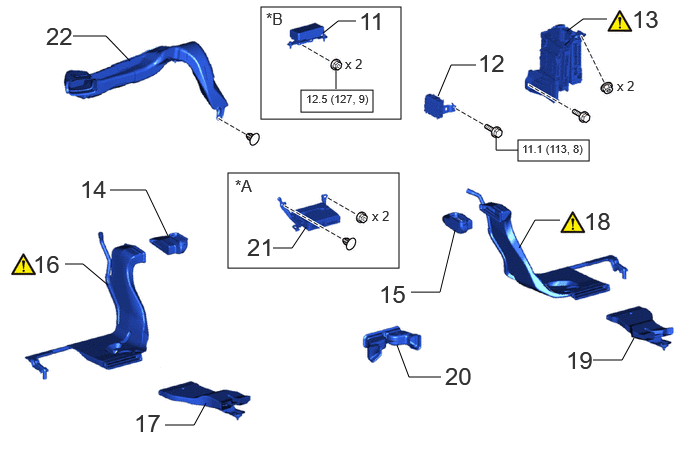
| Procedure | Part Name Code |
|
|
|
|
|---|---|---|---|---|---|
| 11 | DOOR CONTROL BATTERY | 8598A | - | - | - |
| 12 | WINDSHIELD WIPER RELAY ASSEMBLY | 85940 | - | - | - |
| 13 | ECU INTEGRATION BOX RH | 82877 | () |
- | - |
| 14 | REAR NO. 2 AIR DUCT | 87212F | - | - | - |
| 15 | REAR NO. 1 AIR DUCT | 87212 | - | - | - |
| 16 | REAR NO. 4 AIR DUCT | 87212H | () |
- | - |
| 17 | REAR NO. 6 AIR DUCT | 87212K | - | - | - |
| 18 | REAR NO. 3 AIR DUCT | 87212G | () |
- | - |
| 19 | REAR NO. 5 AIR DUCT | 87212J | - | - | - |
| 20 | NO. 1 COOLER AIR DUCT | 88576C | - | - | - |
| 21 | TELEPHONE TRANSCEIVER ASSEMBLY WITH BRACKET | - | - | - | - |
| 22 | NO. 1 HEATER TO REGISTER DUCT SUB-ASSEMBLY | 55084E | - | - | - |
| *A | w/ Telematics Transceiver | *B | w/ Door Control Battery |
|
|
N*m (kgf*cm, ft.*lbf): Specified torque | - | - |
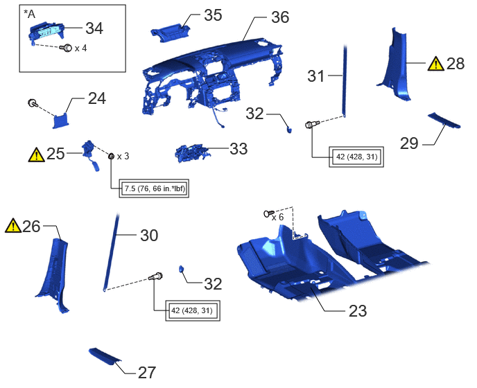
| Procedure | Part Name Code |
|
|
|
|
|---|---|---|---|---|---|
| 23 | FRONT FLOOR CARPET ASSEMBLY | 58510D | - | - | - |
| 24 | AIR CONDITIONING AMPLIFIER ASSEMBLY | 88650N | - | - | - |
| 25 | ACCELERATOR PEDAL(WITH SENSOR) ROD ASSEMBLY | 78110K | () |
- | - |
| 26 | CENTER PILLAR LOWER GARNISH LH | 62414A | () |
- | - |
| 27 | REAR DOOR SCUFF PLATE LH | 67918D | - | - | - |
| 28 | CENTER PILLAR LOWER GARNISH RH | 62413A | () |
- | - |
| 29 | REAR DOOR SCUFF PLATE RH | 67917C | - | - | - |
| 30 | FRONT SEAT OUTER BELT ASSEMBLY LH (FLOOR ANCHOR) | 73220 | - | - | - |
| 31 | FRONT SEAT OUTER BELT ASSEMBLY RH (FLOOR ANCHOR) | 73210 | - | - | - |
| 32 | OUTER LAP BELT ANCHOR COVER | 73233 | - | - | - |
| 33 | STEERING COLUMN ASSEMBLY | 45250 | - | - | - |
| 34 | METER MIRROR SUB-ASSEMBLY | 83108 | - | - | - |
| 35 | LOWER DEFROSTER NOZZLE ASSEMBLY | 55990B | - | - | - |
| 36 | INSTRUMENT PANEL SAFETY PAD | - | - | - | - |
| *A | w/ Headup Display | - | - |
|
|
Tightening torque for "Major areas involving basic vehicle performance such as moving/turning/stopping": N*m (kgf*cm, ft.*lbf) | - | - |
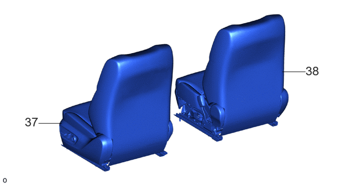
| Procedure | Part Name Code |
|
|
|
|
|---|---|---|---|---|---|
| 37 | FRONT SEAT ASSEMBLY LH | - | - | - | - |
| 38 | FRONT SEAT ASSEMBLY RH | - | - | - | - |
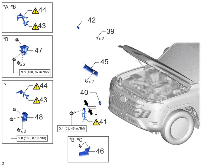
| Procedure | Part Name Code |
|
|
|
|
|---|---|---|---|---|---|
| 39 | HOLE PLUG | - | - | - | - |
| 40 | COOLER PIPE GROMMET | 88897K | - | - | - |
| 41 | NO. 3 AIR CONDITIONING TUBE AND ACCESSORY ASSEMBLY | 88710K | () |
- | - |
| 42 | HEATER GROMMET | 87128 | - | - | - |
| 43 | INLET HEATER WATER HOSE A | - | () |
- | - |
| 44 | OUTLET HEATER WATER HOSE A | - | () |
- | - |
| 45 | OUTER DASH PANEL INSULATOR | 55223A | - | - | - |
| 46 | REAR ENGINE SIDE UNDER COVER ASSEMBLY LH | 51470C | - | - | - |
| 47 | HEATER PIPING COVER | 87237 | - | - | - |
| 48 | NO. 1 HEATER COVER | 87114E | - | - | - |
| *A | for 1GR-FE | *B | for V35A-FTS |
| *C | for F33A-FTS | - | - |
|
|
N*m (kgf*cm, ft.*lbf): Specified torque | ● | Non-reusable part |

|
Compressor oil ND-OIL 8 or equivalent | - | - |
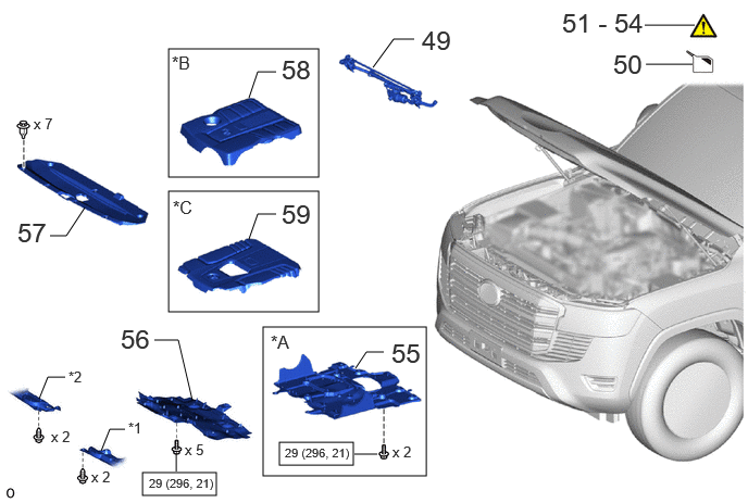
| Procedure | Part Name Code |
|
|
|
|
|---|---|---|---|---|---|
| 49 | FRONT WIPER MOTOR AND LINK | - | - | - | - |
| 50 | ADD ENGINE COOLANT | - | - | () |
- |
| 51 | INSPECT FOR COOLANT LEAK | - | () |
- | - |
| 52 | CHARGE AIR CONDITIONING SYSTEM WITH REFRIGERANT | - | () |
- | - |
| 53 | WARM UP ENGINE | - | () |
- | - |
| 54 | INSPECT FOR REFRIGERANT LEAK | - | () |
- | - |
| 55 | NO. 2 ENGINE UNDER COVER ASSEMBLY | 51420 | - | - | - |
| 56 | NO. 1 ENGINE UNDER COVER ASSEMBLY | 51410 | - | - | - |
| 57 | UPPER RADIATOR SUPPORT SEAL | 53292A | - | - | - |
| 58 | V-BANK COVER SUB-ASSEMBLY | 11209 | - | - | - |
| 59 | NO. 1 ENGINE COVER SUB-ASSEMBLY | 12601B | - | - | - |
| *A | for 1GR-FE | *B | for V35A-FTS |
| *C | for F33A-FTS | - | - |
| *1 | ENGINE SIDE COVER SUB-ASSEMBLY LH | *2 | ENGINE SIDE COVER SUB-ASSEMBLY RH |
|
|
N*m (kgf*cm, ft.*lbf): Specified torque | - | - |
CAUTION / NOTICE / HINT
- HINT:
-
A bolt without a torque specification is shown in the standard bolt chart.
-
Click hereGeneral>SPECIFICATIONS>STANDARD BOLT>SPECIFIED TORQUE FOR STANDARD BOLTS
PROCEDURE

 88536 1.INSTALL NO. 1 COOLING UNIT BRACKET
88536A 2.INSTALL NO. 2 COOLING UNIT BRACKET
3.INSTALL AIR CONDITIONER UNIT ASSEMBLY
- Torque:
- 9.8 N*m (100 kgf*cm, 87 in.*lbf)
88539G 4.INSTALL COOLER UNIT DRAIN HOSE GROMMET
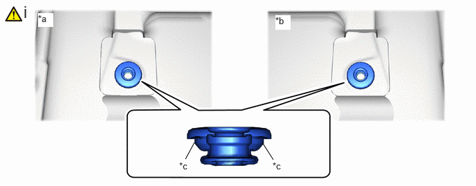
| *a | Driver Side | *b | Passenger Side |
| *c | Lip | - | - |
Press the entire upper surface of the new cooler unit drain hose grommet, and fit the entire circumference of the lip to the hole.
- NOTICE:
-
·
If the drain cooler hose is disconnected from the cooler unit drain hose grommet, make sure to replace the cooler unit drain hose grommet with a new one. Failure to do so may lead to water ingress.
·Make sure that the entire lip of the cooler unit drain hose grommet is securely engaged to the vehicle body.
5.INSTALL INSTRUMENT PANEL REINFORCEMENT ASSEMBLY WITH AIR CONDITIONING UNIT ASSEMBLY
|
|
|
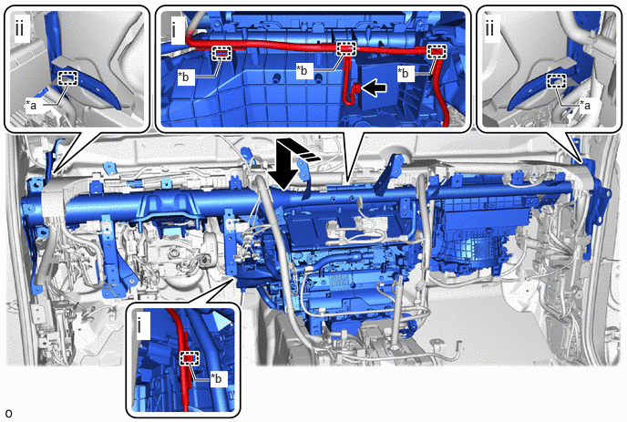
| *a | Guide | *b | Clamp |

|
Install to Guide by Inserting to the End | - | - |
Connect the connector and attach the clamp.
Install the instrument panel reinforcement assembly with air conditioning unit assembly to the guide as shown in the illustration.
- NOTICE:
-
·
Be careful not to damage the internal components of the instrument panel reinforcement assembly and air conditioning unit assembly on the glass etc. Only perform installation after first taking the appropriate actions.
·Make sure that both parts are securely installed to the guide.
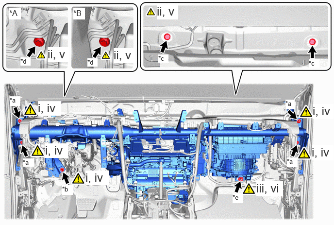
| *A | for 1GR-FE | *B | for V35A-FTS, F33A-FTV |
| *a | Bolt (A) | *b | Bolt (B) |
| *c | Bolt (C) | *d | Bolt (D) |
| *e | Nut | - | - |
Temporarily install the 4 bolts (A) and bolt (B).
Temporarily install the 2 bolts (C) and bolt (D).
Temporarily install the nut.
Tighten the 4 bolts (A) and bolt (B).
- Torque:
- Bolt (A) : 25 N*m (255 kgf*cm, 18 ft.*lbf)
- Bolt (B) : 15 N*m (153 kgf*cm, 11 ft.*lbf)
Tighten the 2 bolts (C) and bolt (D).
- Torque:
- 25 N*m (255 kgf*cm, 18 ft.*lbf)
Tighten the nut.
- Torque:
- 9.8 N*m (100 kgf*cm, 87 in.*lbf)
82141 6.CONNECT INSTRUMENT PANEL WIRE
- Torque:
- Bolt : 10 N*m (102 kgf*cm, 7 ft.*lbf)
55307C 7.INSTALL NO. 2 INSTRUMENT PANEL BRACE SUB-ASSEMBLY
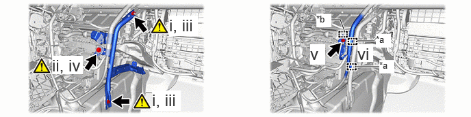
| *a | Clamp | *b | Guide |
Temporarily install the No. 2 instrument panel brace sub-assembly with the nut and bolt.
Temporarily install the screw.
Tighten the 2 nuts and bolt.
- Torque:
- Nut : 18 N*m (184 kgf*cm, 13 ft.*lbf)
- Bolt : 16 N*m (163 kgf*cm, 12 ft.*lbf)
Tighten the screw.
Attach the guide and connect the ground wire with the bolt.
- Torque:
- 10 N*m (102 kgf*cm, 7 ft.*lbf)
Attach the clamp.
55306A 8.INSTALL NO. 1 INSTRUMENT PANEL BRACE SUB-ASSEMBLY
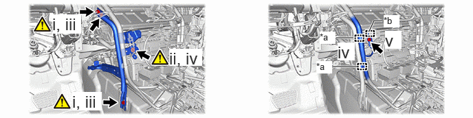
| *a | Clamp | *b | Guide |
Temporarily install the No. 1 instrument panel brace sub-assembly with the 2 nuts and bolt.
- NOTICE:
-
Check for the No. 1 instrument panel brace sub-assembly and air conditioner harness assembly do not interfere.
Temporarily install the screw.
Tighten the 2 nuts and bolt.
- Torque:
- Nut : 18 N*m (184 kgf*cm, 13 ft.*lbf)
- Bolt : 16 N*m (163 kgf*cm, 12 ft.*lbf)
Tighten the screw.
Attach the guide and connect the ground wire with the bolt.
- Torque:
- 10 N*m (102 kgf*cm, 7 ft.*lbf)
Attach the clamp.
82213E 9.INSTALL HEATER BLOWER WIRE (w/ PTC Heater)
87201 10.INSTALL NO. 1 AIR DUCT SUB-ASSEMBLY
8598A 11.INSTALL DOOR CONTROL BATTERY (w/ Door Control Battery)
85940 12.INSTALL WINDSHIELD WIPER RELAY ASSEMBLY
82877 13.INSTALL ECU INTEGRATION BOX RH
|
|
Click here() |
87212F 14.INSTALL REAR NO. 2 AIR DUCT
87212 15.INSTALL REAR NO. 1 AIR DUCT
87212H 16.INSTALL REAR NO. 4 AIR DUCT
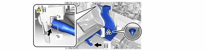
| *a | Protrusion | *b | Cutout |
Insert the rear No. 4 air duct to the No. 2 air duct and attach the clip.
Align the cutout of the drain hose with the protrusion of the heater case and connect the drain hose.
Connect the drain hose to the cooler unit drain hose grommet.
87212K 17.INSTALL REAR NO. 6 AIR DUCT
87212G 18.INSTALL REAR NO. 3 AIR DUCT
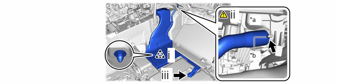
| *a | Protrusion | *b | Cutout |
Insert the rear No. 3 air duct to the No. 1 air duct and attach the clip.
Align the cutout of the drain hose with the protrusion of the heater case and connect the drain hose.
Connect the drain hose to the cooler unit drain hose grommet.
87212J 19.INSTALL REAR NO. 5 AIR DUCT
88576C 20.INSTALL NO. 1 COOLER AIR DUCT
21.INSTALL TELEPHONE TRANSCEIVER ASSEMBLY WITH BRACKET (w/ Telematics Transceiver)
55084E 22.INSTALL NO. 1 HEATER TO REGISTER DUCT SUB-ASSEMBLY
58510D 23.INSTALL FRONT FLOOR CARPET ASSEMBLY
88650N 24.INSTALL AIR CONDITIONING AMPLIFIER ASSEMBLY
78110K 25.INSTALL ACCELERATOR PEDAL(WITH SENSOR) ROD ASSEMBLY
|
|
·
for 1GR-FE: Click here(
·
for V35A-FTS: Click here(
·
for F33A-FTV: Click here( |
62414A 26.INSTALL CENTER PILLAR LOWER GARNISH LH
|
|
Click here() |
67918D 27.INSTALL REAR DOOR SCUFF PLATE LH
62413A 28.INSTALL CENTER PILLAR LOWER GARNISH RH
Use the same procedure described for the LH side.
67917C 29.INSTALL REAR DOOR SCUFF PLATE RH
73220 30.INSTALL FRONT SEAT OUTER BELT ASSEMBLY LH (FLOOR ANCHOR)
73210 31.INSTALL FRONT SEAT OUTER BELT ASSEMBLY RH (FLOOR ANCHOR)
Use the same procedure described for the LH side.
73233 32.INSTALL OUTER LAP BELT ANCHOR COVER
45250 33.INSTALL STEERING COLUMN ASSEMBLY
for Manual Tilt and Manual Telescopic Steering Column:
for Power Tilt and Power Telescopic Steering Column:
83108 34.INSTALL METER MIRROR SUB-ASSEMBLY (w/ Headup Display)
55990B 35.INSTALL LOWER DEFROSTER NOZZLE ASSEMBLY
36.INSTALL INSTRUMENT PANEL SAFETY PAD
37.INSTALL FRONT SEAT ASSEMBLY LH
for Manual Seat:
Click hereVehicle Interior>SEAT>FRONT SEAT ASSEMBLY (for Manual Seat)>INSTALLATION
for Power Seat:
Click hereVehicle Interior>SEAT>FRONT SEAT ASSEMBLY (for Power Seat)>INSTALLATION
38.INSTALL FRONT SEAT ASSEMBLY RH
Use the same procedure described for the LH side.
39.INSTALL HOLE PLUG
88897K 40.INSTALL COOLER PIPE GROMMET
88710K 41.CONNECT NO. 3 AIR CONDITIONING TUBE AND ACCESSORY ASSEMBLY
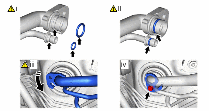
|
|
Rotate in this Direction | - | - |
Sufficiently apply compressor oil to a new O-rings and the fitting surface of the No. 3 air conditioning tube and accessory assembly.
- Compressor Oil:
-
ND-OIL 8 or equivalent
Install the 2 O-rings to the No. 3 air conditioning tube and accessory assembly.
- NOTICE:
-
Keep the O-ring and O-ring fitting surface free of foreign matter.
Connect the No. 3 air conditioning tube and accessory assembly and rotate the 1-point tightening plate as shown in the illustration.
- NOTICE:
-
·
Do not apply excessive force to the No. 3 air conditioning tube and accessory assembly.
·Make sure not to cut the O-ring while installing it. (Cut O-rings cannot be installed.)
Install the bolt.
- Torque:
- 5.4 N*m (55 kgf*cm, 48 in.*lbf)
87128 42.INSTALL HEATER GROMMET
43.CONNECT INLET HEATER WATER HOSE A
for 1GR-FE:
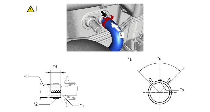
| *1 | Inlet Heater Water Hose A | *2 | Hose Clip |
| *a | View A | *b | Marking |
| *c | Hose Clip Installation Angle (90° From Above the Vehicle) | *d | Hose Clip Installation Range 20 mm (0.787 in.)) |
| *e | Stopper | - | - |
Connect the inlet heater water hose A with its marking facing upward and install the hose clip within the range shown in the illustration.
- NOTICE:
-
Do not apply excessive force to the inlet heater water hose A.
for V35A-FTS:
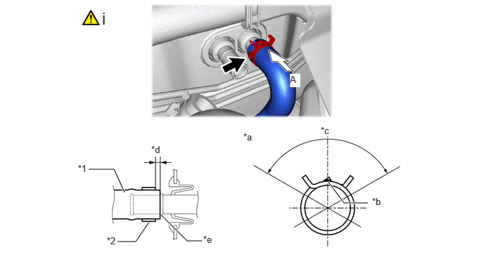
| *1 | Heater Water Hose Inlet A | *2 | Hose Clip |
| *a | View A | *b | Marking |
| *c | Hose Clip Installation Angle (120° From Above the Vehicle) | *d | Hose Clip Installation Range (1 to 5 mm (0.0394 to 0.196 in.)) |
| *e | Stopper | - | - |
Connect the inlet heater water hose A with its marking facing upward and install the hose clip within the range shown in the illustration.
- NOTICE:
-
Do not apply excessive force to the inlet heater water hose A.
for F33A-FTV:
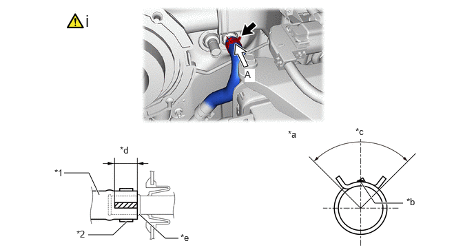
| *1 | Inlet Heater Water Hose A | *2 | Hose Clip |
| *a | View A | *b | Marking |
| *c | Hose Clip Installation Angle (90° From Above the Vehicle) | *d | Hose Clip Installation Range 20 mm (0.787 in.)) |
| *e | Stopper | - | - |
Connect the inlet heater water hose A with its marking facing upward and install the hose clip within the range shown in the illustration.
- NOTICE:
-
Do not apply excessive force to the inlet heater water hose A.
44.CONNECT OUTLET HEATER WATER HOSE A
for 1GR-FE:
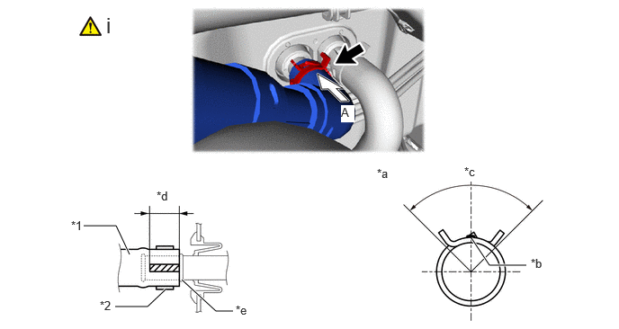
| *1 | Outlet Heater Water Hose A | *2 | Hose Clip |
| *a | View A | *b | Marking |
| *c | Hose Clip Installation Angle (90° From Above the Vehicle) | *d | Hose Clip Installation Range 20 mm (0.787 in.)) |
| *e | Stopper | - | - |
Connect the outlet heater water hose A with its marking facing upward and install the hose clip within the range shown in the illustration.
- NOTICE:
-
Do not apply excessive force to the outlet heater water hose A.
for V35A-FTS:
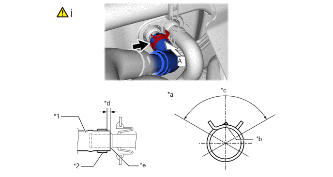
| *1 | Outlet Heater Water Hose A | *2 | Hose Clip |
| *a | View A | *b | Marking |
| *c | Hose Clip Installation Angle (120° From Above the Vehicle) | *d | Hose Clip Installation Range (1 to 5 mm (0.0394 to 0.196 in.)) |
| *e | Stopper | - | - |
Connect the outlet heater water hose A with its marking facing upward and install the hose clip within the range shown in the illustration.
- NOTICE:
-
Do not apply excessive force to the outlet heater water hose A.
for F33A-FTV:
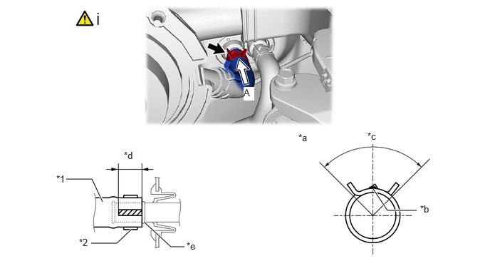
| *1 | Outlet Heater Water Hose A | *2 | Hose Clip |
| *a | View A | *b | Marking |
| *c | Hose Clip Installation Angle (90° From Above the Vehicle) | *d | Hose Clip Installation Range 20 mm (0.787 in.)) |
| *e | Stopper | - | - |
Connect the outlet heater water hose A with its marking facing upward and install the hose clip within the range shown in the illustration.
- NOTICE:
-
Do not apply excessive force to the outlet heater water hose A.
55223A 45.CONNECT OUTER DASH PANEL INSULATOR
51470C 46.CONNECT REAR ENGINE SIDE UNDER COVER ASSEMBLY LH (for V35A-FTS, F33A-FTV)
87237 47.INSTALL HEATER PIPING COVER (for V35A-FTS)
- Torque:
- 9.8 N*m (100 kgf*cm, 87 in.*lbf)
87114E 48.INSTALL NO. 1 HEATER COVER (for F33A-FTV)
- Torque:
- 9.8 N*m (100 kgf*cm, 7 ft.*lbf)
49.INSTALL FRONT WIPER MOTOR AND LINK
50.ADD ENGINE COOLANT
for 1GR-FE:
for V35A-FTS:
for F33A-FTV:
51.INSPECT FOR COOLANT LEAK
for 1GR-FE:
Click hereEngine / Hybrid System>1GR-FE (COOLING)>COOLING SYSTEM>ON-VEHICLE INSPECTION
for V35A-FTS:
Click hereEngine / Hybrid System>V35A-FTS (COOLING)>COOLING SYSTEM>ON-VEHICLE INSPECTION
for F33A-FTV:
Click hereEngine / Hybrid System>F33A-FTV (COOLING)>COOLING SYSTEM>ON-VEHICLE INSPECTION
52. CHARGE AIR CONDITIONING SYSTEM WITH REFRIGERANT
53.WARM UP ENGINE
54.INSPECT FOR REFRIGERANT LEAK
51420 55.INSTALL NO. 2 ENGINE UNDER COVER ASSEMBLY (for 1GR-FE)
51410 56.INSTALL NO. 1 ENGINE UNDER COVER ASSEMBLY
for 1GR-FE:
Click hereEngine / Hybrid System>1GR-FE (LUBRICATION)>OIL LEVEL SENSOR>INSTALLATION
for V35A-FTS:
Click hereEngine / Hybrid System>V35A-FTS (LUBRICATION)>OIL PAN AND OIL LEVEL SENSOR>INSTALLATION
for F33A-FTV:
Click hereEngine / Hybrid System>F33A-FTV (LUBRICATION)>OIL PAN AND OIL LEVEL SENSOR>INSTALLATION
53292A 57.INSTALL UPPER RADIATOR SUPPORT SEAL
11209 58.INSTALL V-BANK COVER SUB-ASSEMBLY (for V35A-FTS)
12601B 59.INSTALL NO. 1 ENGINE COVER SUB-ASSEMBLY (for F33A-FTV)