F33A-FTV ENGINE CONTROL ECD SYSTEM(w/o DPF) P12B100 2nd Turbocharger/Supercharger Overboost Condition
DESCRIPTION
Refer to DTC P12AC12.
Click hereEngine / Hybrid System>F33A-FTV (ENGINE CONTROL)>ECD SYSTEM (w/o DPF)>P12AC12
Refer to DTC P25F812.
Click hereEngine / Hybrid System>F33A-FTV (ENGINE CONTROL)>ECD SYSTEM (w/o DPF)>P25F812
| DTC No. | Detection Item | DTC Detection Condition | Trouble Area | MIL | Note |
|---|---|---|---|---|---|
| P12B100 | 2nd Turbocharger/Supercharger Overboost Condition | During single turbo operation or when switching from twin turbo to single turbo, a difference between atmospheric pressure and 2nd compressor outlet pressure of 25 kPa or less continues for 4 seconds or more. (1 trip detection logic) |
·
No. 2 vacuum switching valve assembly (for intake air control valve)
·
Intake air control valve
·
No. 1 vacuum switching valve assembly (for exhaust control valve)
·
Actuator assembly (for exhaust control valve)
·
Exhaust control valve (No. 2 turbocharger sub-assembly)
·
Atmospheric pressure sensor (ECM)
·
Manifold absolute pressure sensor (2nd turbocharger outlet side) |
Comes on | SAE Code: P12B1 |
| DTC No. | Data List |
|---|---|
| P12B100 |
·
Atmospheric Pressure
·
Intake Manifold Absolute Pressure
·
2nd Turbocharger/Supercharger Outlet Pressure
·
Air Control Valve Current-Carrying Request
·
Exhaust Control Valve Current-Carrying Request |
CONFIRMATION DRIVING PATTERN
| DTC No. | DTC Detection Drive Pattern |
|---|---|
| P12B100 | After warming up the engine, fully depress the accelerator pedal for 6 seconds or more after reaching a speed of 20 km/h while fixed in the 2nd gear position. |
CAUTION / NOTICE / HINT
- NOTICE:
-
·
Inspect the fuses of circuits related to this system before performing the following procedure.
·After replacing the ECM, the new ECM needs registration (Click here Engine / Hybrid System>F33A-FTV (ENGINE CONTROL)>ECD SYSTEM (w/o DPF)>REGISTRATION) and initialization (Click here Engine / Hybrid System>F33A-FTV (ENGINE CONTROL)>ECD SYSTEM (w/o DPF)>INITIALIZATION).
- HINT:
-
Read freeze frame data using the GTS. Freeze frame data records the engine condition when malfunctions are detected. When troubleshooting, freeze frame data can help determine if the vehicle was moving or stationary, if the engine was warmed up or not, and other data from the time the malfunction occurred.
PROCEDURE
Check the DTC judgment result.
- Result:
-
Result Proceed to P12B100 is output A DTC P12B100 and other DTCs are output* B
- HINT:
-
*: If any other DTCs (CAN communication malfunctions or open/short circuits) are output, perform troubleshooting for those DTCs first.
A
B
Check that there are no malfunctions in intake/exhaust system piping such as damage, air suction or exhaust leaks in the engine room.
- Result:
-
Proceed to OK NG
OK
NG
Using the table, read the normal atmospheric pressure value for the applicable altitude and temperature.
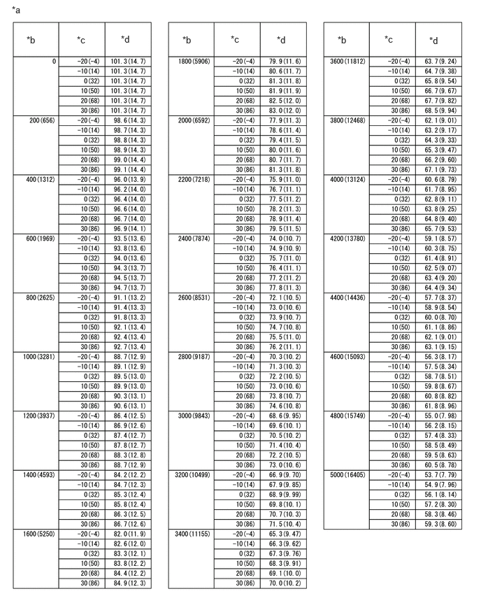
| *a | Altitude, Temperature and Atmospheric Pressure Correlation Table | *b | Altitude (m (ft.)) |
| *c | Temperature (°C (°F)) | *d | Atmospheric Pressure (kPa (psi)) |
- HINT:
-
·
Standard atmospheric pressure is approximately 101 kPa(abs) [14.65 psi(abs)].
·For every 100 m (328 ft.) increase in altitude, atmospheric pressure drops by approximately 1 kPa [0.15 psi]. This varies by weather.
Compare the Atmospheric pressure value in the Data List with the normal atmospheric value from the table.
- Powertrain > Engine > Data List
-
Tester Display Atmospheric Pressure - 50003 372 229
- Result:
-
Result Proceed to Difference between Atmospheric Pressure in the Data List and normal atmospheric pressure value is 10 kPa (1.45 psi) or more. A Except above B
A
B
Check the manifold absolute pressure sensor (2nd turbocharger outlet side).
- Result:
-
Proceed to OK NG
OK
NG
Click hereEngine / Hybrid System>F33A-FTV (ENGINE CONTROL)>MANIFOLD ABSOLUTE PRESSURE SENSOR>REMOVAL
Remove the vacuum hose connected to the vacuum pump and install the vacuum pump to the vacuum hose.
Enter the following menus: Powertrain / Engine / Active Test / Activate the Air Control Valve.
- Powertrain > Engine > Active Test
-
Tester Display Activate the Air Control Valve - 50004 372 42040
Perform the Active Test.
Check that the link on the intake air control valve actuator operates when negative pressure is applied using the vacuum pump.
- OK:
-
The link on the intake air control valve actuator operates.
- Result:
-
Proceed to OK NG
OK
NG
Remove the vacuum hose connected to the vacuum pump and install the vacuum pump to the vacuum hose.
Enter the following menus: Powertrain / Engine / Active Test / Activate the Exhaust Control Valve.
- Powertrain > Engine > Active Test
-
Tester Display Activate the Exhaust Control Valve - 50004 372 42041
Perform the Active Test.
Check that the actuator assembly link of the exhaust control valve operates when negative pressure is applied using the vacuum pump.
- OK:
-
The actuator assembly link of the exhaust control valve operates.
- Result:
-
Proceed to OK NG
OK
NG
Inspect the vacuum pump assembly.
Click hereBrake>BRAKE SYSTEM (OTHER)>VACUUM PUMP>ON-VEHICLE INSPECTION
- Result:
-
Proceed to OK NG
OK
NG
Clear the DTCs.
- Powertrain > Engine > Clear DTCs
- 50002 372
Turn the ignition switch off and wait for at least 30 seconds.
- Result:
-
Proceed to NEXT
NEXT
After warming up the engine, fully depress the accelerator pedal for 6 seconds or more after reaching a speed of 20 km/h while fixed in the 2nd gear position.
- CAUTION:
-
When performing the confirmation driving pattern, obey all speed limits and traffic laws.
Enter the following menus: Powertrain / Engine / Trouble Codes.
- Powertrain > Engine > Trouble Codes
- 50001 372
Read the DTCs.
- Result:
-
Result Proceed to P12B100 is output A DTCs are not output B
A
B
Remove the intake air control valve.
Check that the intake air control valve is fully closed.
- OK:
-
The intake air control valve is fully closed.
- Result:
-
Proceed to OK NG
OK
NG
Repair or replace the malfunctioning part in the intake/exhaust system.
- Result:
-
Proceed to NEXT
NEXT
Inspect the No. 1 vacuum switching valve assembly (for exhaust control valve).
Click hereEngine / Hybrid System>F33A-FTV (INTAKE / EXHAUST)>VACUUM SWITCHING VALVE>INSPECTION
- Result:
-
Proceed to OK NG
OK
NG
Check the vacuum hose connections.
- OK:
-
Vacuum hose is connected correctly and is not damaged.
- Result:
-
Proceed to OK NG
OK
NG
Remove the vacuum hose from the actuator assembly (for exhaust control valve) of the No. 2 turbocharger sub-assembly.
Connect the vacuum pump to the exhaust control valve actuator.
Check that the exhaust control valve actuator rod operates smoothly when negative pressure is applied and that the rod strokes when negative pressure is released.
- OK:
-
The exhaust control valve actuator rod operates and the rod strokes when negative pressure is released.
- Result:
-
Proceed to OK NG
OK
NG
Remove the compressor housing installation bolt from the No. 2 turbocharger sub-assembly, and remove the E-ring from the link on the exhaust control valve actuator.
Disconnect the link on the exhaust control valve actuator.
Connect the vacuum pump to the exhaust control valve actuator.
Check that the exhaust control valve actuator rod operates smoothly when negative pressure is applied.
- OK:
-
The exhaust control valve actuator rod operates smoothly.
- Result:
-
Proceed to OK NG
OK
NG
Inspect the No. 2 vacuum switching valve assembly (for intake air control valve).
Click hereEngine / Hybrid System>F33A-FTV (INTAKE / EXHAUST)>VACUUM SWITCHING VALVE>INSPECTION
- Result:
-
Proceed to OK NG
OK
NG
Check the vacuum hose connections.
- OK:
-
Vacuum hose is connected correctly and is not damaged.
- Result:
-
Proceed to OK NG
OK
NG
Remove the vacuum hose from the intake air control value actuator.
Connect the vacuum pump to the intake air control valve actuator.
Check that the intake air control valve operates smoothly when negative pressure is applied, and that the valve is fully closed when negative pressure is released.
- OK:
-
The intake air control valve operates smoothly, and the valve is fully closed when negative pressure is released.
- Result:
-
Proceed to OK NG
OK
NG