1VD-FTV ENGINE CONTROL ECD SYSTEM P0234 Turbocharger / Supercharger Overboost Condition P0299 Turbocharger / Supercharger Underboost P1251 Turbocharger / Supercharger Overboost Condition (Too High)
DESCRIPTION
The variable nozzle vane type turbocharger operates the vacuum type actuator and controls the nozzle vane by using the VRV, which is controlled by the ECM. At a low to medium vehicle speed, when the nozzle vane moves in the closing direction and the exhaust gas rate of flow becomes faster, the engine torque increases. At a high vehicle speed, when the nozzle vane moves in the opening direction, the exhaust pressure decreases. This leads to improved fuel consumption and engine output.
| DTC No. | Detection Item | DTC Detection Condition | Trouble Area | MIL | Memory |
|---|---|---|---|---|---|
| P0234 | Turbocharger / Supercharger Overboost Condition | When turbocharger boost pressure continues to be higher than ECM's target boost pressure. (1 trip detection logic) |
·
Vacuum regulating valve
·
Turbocharger sub-assembly
·
Vacuum hose
·
EGR valve assembly
·
Mass air flow meter
·
ECM |
Comes on | DTC stored |
| P0299 | Turbocharger / Supercharger Underboost | When turbocharger boost pressure continues to be lower than ECM's target boost pressure. (2 trip detection logic) |
·
Vacuum regulating valve
·
Turbocharger sub-assembly
·
Vacuum hose
·
EGR valve assembly
·
Mass air flow meter
·
ECM |
Comes on | DTC stored |
| P1251 | Turbocharger / Supercharger Overboost Condition (Too High) | When turbocharger boost pressure is higher than boost pressure for a short time in which there was possibility of engine damage. (1 trip detection logic) |
·
Vacuum regulating valve
·
Turbocharger sub-assembly
·
Vacuum hose
·
EGR valve assembly
·
Mass air flow meter
·
ECM |
Comes on | DTC stored |
WIRING DIAGRAM
Refer to DTC P0045.
Click hereEngine / Hybrid System>1VD-FTV (ENGINE CONTROL)>ECD SYSTEM>P0045
CAUTION / NOTICE / HINT
- NOTICE:
-
After replacing the ECM, the new ECM needs registration (See page Engine / Hybrid System>1VD-FTV (ENGINE CONTROL)>ECD SYSTEM>REGISTRATION) and initialization (See page Engine / Hybrid System>1VD-FTV (ENGINE CONTROL)>ECD SYSTEM>INITIALIZATION).
- HINT:
-
Read freeze frame data using the GTS. Freeze frame data records the engine condition when malfunctions are detected. When troubleshooting, freeze frame data can help determine if the vehicle was moving or stationary, if the engine was warmed up or not, and other data from the time the malfunction occurred.
PROCEDURE
Connect the GTS to the DLC3.
Turn the ignition switch ON and turn the GTS ON.
Enter the following menus: Powertrain / Engine and ECT / Trouble Codes.
- Powertrain > Engine and ECT > Trouble Codes
- 50001 61
Read DTCs.
- Result:
-
Result Proceed to P0234, P0299 and/or P1251 are output A P0234, P0299 and/or P1251 and other DTCs are output B
A
B
Check the intake and exhaust system modifications.
- OK:
-
No modifications.
- Result:
-
Proceed to OK NG
OK
NG
Check the connections of the vacuum hoses of the turbocharger system.
- OK:
-
The vacuum hoses are correctly connected.
- Result:
-
Proceed to OK NG
OK
NG
Using a three-way connector, connect a vacuum gauge to the hose between the vacuum regulating valve (VRV) and turbocharger.
Warm up the engine coolant temperature to above 75°C (167°F).
Check the vacuum while idling.
- Result:
-
Vacuum Proceed to 0 kPa (0 mmHg, 0 in.Hg) to 50 kPa (375 mmHg, 14.8 in.Hg) A Above 50 kPa (375 mmHg, 14.8 in.Hg) B
A
B
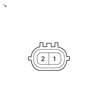
| *a | Component without harness connected (Vacuum Regulating Valve) |
Disconnect the C91 Vacuum Regulating Valve (VRV) connector.
Measure the resistance according to the value(s) in the table below.
- Standard resistance:
-
Tester Connection Condition Specified Condition 1 - 2 20°C (68°F) 11 to 13 Ω
- Result:
-
Proceed to OK NG
OK
NG
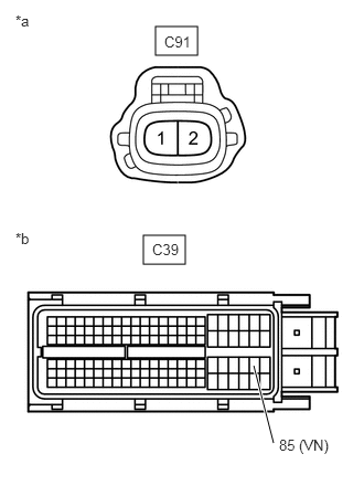
| *a | Front view of wire harness connector (to Vacuum Regulating Valve) |
| *b | Front view of wire harness connector (to ECM) |
Disconnect the C91 VRV connector.
Disconnect the C39 ECM connector.
Measure the resistance according to the value(s) in the table below.
- Standard resistance:
-
Tester Connection Condition Specified Condition C91-2 - C39-85 (VN) Always Below 1 Ω C91-2 or C39-85 (VN) - Body ground Always 10 kΩ or higher
- Result:
-
Proceed to OK NG
OK
NG
Check the turbocharger.
- Result:
-
Proceed to OK NG
OK
NG
Click hereEngine / Hybrid System>1VD-FTV (INTAKE / EXHAUST)>EXHAUST MANIFOLD W/ TURBOCHARGER (w/o DPF)>REMOVAL
Check the EGR valve (No. 1 or No. 2).
Click hereEngine / Hybrid System>1VD-FTV (EMISSION CONTROL)>EGR VALVE (w/o DPF)>INSPECTION
- Result:
-
Proceed to OK NG
OK
NG
Inspect the mass air flow meter.
Click hereEngine / Hybrid System>1VD-FTV (ENGINE CONTROL)>MASS AIR FLOW METER>ON-VEHICLE INSPECTION
- Result:
-
Proceed to OK NG
OK
NG