DOOR / HATCH REAR DOOR DISASSEMBLY
CAUTION / NOTICE / HINT
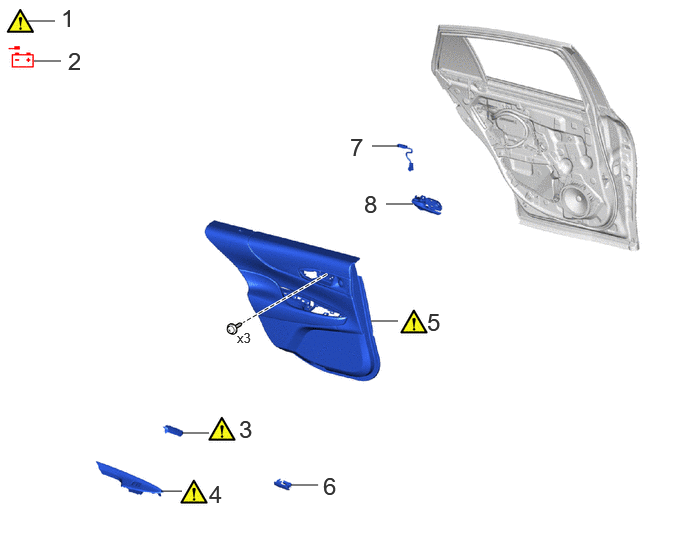
| Procedure | Part Name Code | 
|

|

|
|
|---|---|---|---|---|---|
| 1 | PRECAUTION | - | ( ) |
- | - |
| 2 | DISCONNECT CABLE FROM NEGATIVE AUXILIARY BATTERY TERMINAL | - | - | - | - |
| 3 | REAR DOOR INSIDE HANDLE BEZEL PLUG | 69284D | ()
|
- | - |
| 4 | REAR POWER WINDOW REGULATOR SWITCH ASSEMBLY WITH REAR DOOR ARMREST BASE PANEL | - | ()
|
- | - |
| 5 | REAR DOOR TRIM BOARD SUB-ASSEMBLY | 67604 | ()
|
- | - |
| 6 | COURTESY LIGHT ASSEMBLY | 81230 | - | - | - |
| 7 | NO. 2 INTERIOR ILLUMINATION LIGHT ASSEMBLY | 81080V | - | - | - |
| 8 | REAR DOOR INSIDE HANDLE SUB-ASSEMBLY | 69206C | - | - | - |
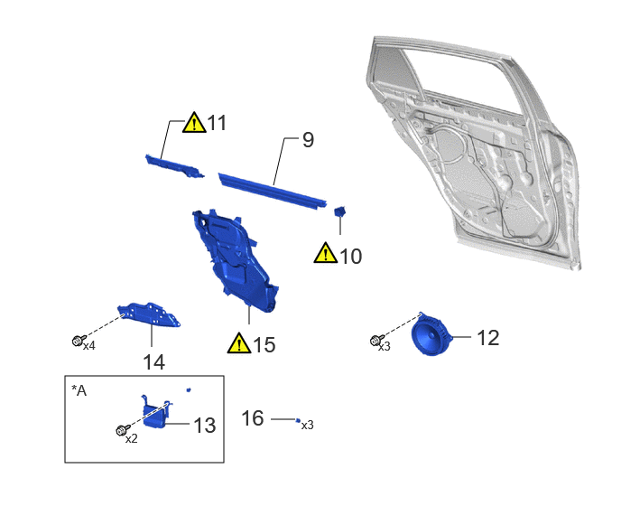
| Procedure | Part Name Code |
|
|
|
|
|---|---|---|---|---|---|
| 9 | REAR DOOR GLASS WEATHERSTRIP INNER | 68174A | - | - | - |
| 10 | REAR DOOR BELT FRONT SEAL | 68197A | ()
|
- | - |
| 11 | REAR DOOR BELT REAR SEAL | 68199 | ()
|
- | - |
| 12 | REAR SPEAKER ASSEMBLY | 86160B | - | - | - |
| 13 | MULTIPLEX NETWORK DOOR REAR ECU | 89225 | - | - | - |
| 14 | REAR DOOR ARMREST SET BRACKET | 67646A | - | - | - |
| 15 | REAR DOOR SERVICE HOLE COVER | 67842E | ()
|
- | - |
| 16 | HOLE PLUG | - | - | - | - |
| *A | w/ Double Locking System | - | - |
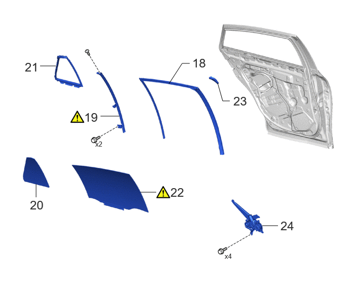
| Procedure | Part Name Code |
|
|
|
|
|---|---|---|---|---|---|
| 17 | REAR DOOR GLASS RUN | 68152C | - | - | - |
| 18 | REAR DOOR WINDOW DIVISION BAR SUB-ASSEMBLY | 67408E | ()
|
- | - |
| 19 | REAR DOOR QUARTER WINDOW GLASS | 68124B | - | - | - |
| 20 | REAR DOOR QUARTER WINDOW WEATHERSTRIP | 68189 | - | - | - |
| 21 | REAR DOOR GLASS SUB-ASSEMBLY | 68104 | ()
|
- | - |
| 22 | REAR DOOR FRAME GARNISH | 67674B | - | - | - |
| 23 | REAR DOOR WINDOW REGULATOR SUB-ASSEMBLY | 69804 | - | - | - |
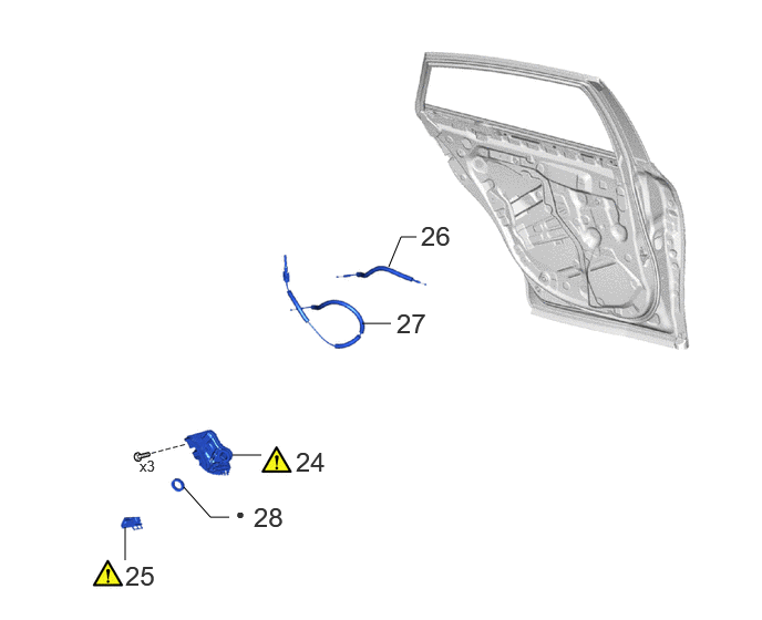
| Procedure | Part Name Code |
|
|
|
|
|---|---|---|---|---|---|
| 24 | REAR DOOR WITH MOTOR LOCK ASSEMBLY | 69060A | ()
|
- | - |
| 25 | REAR DOOR LOCK COVER SUB-ASSEMBLY | 69038A | ()
|
- | - |
| 26 | OPEN LEVER REAR DOOR LOCK REMOTE CONTROL CABLE | 69730M | - | - | - |
| 27 | LOCK / UNLOCK KNOB REAR DOOR INSIDE LOCKING CABLE | 69770E | - | - | - |
| 28 | DOOR LOCK WIRING HARNESS SEAL | 69318D | - | - | - |
| ● | Non-reusable part | - | - |
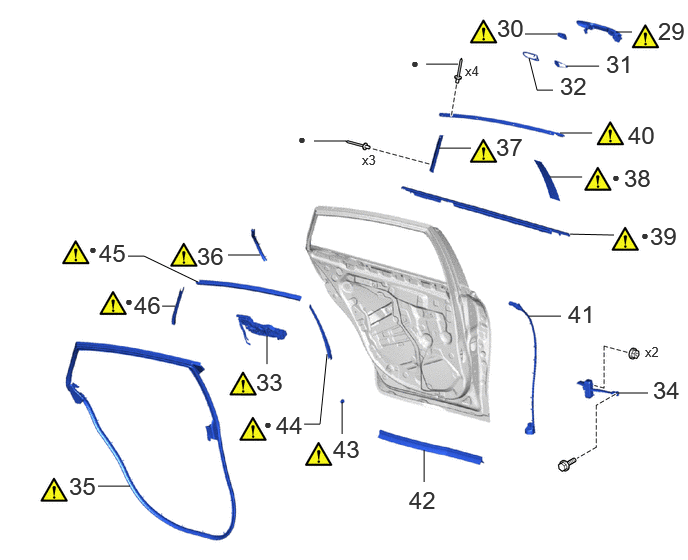
| Procedure | Part Name Code |
|
|
|
|
|---|---|---|---|---|---|
| 29 | REAR DOOR OUTSIDE HANDLE ASSEMBLY | 69240 | ()
|
- | - |
| 30 | REAR DOOR OUTSIDE HANDLE COVER | 69227L | ()
|
- | - |
| 31 | REAR DOOR OUTSIDE HANDLE FRONT PAD | 69241G | - | - | - |
| 32 | REAR DOOR OUTSIDE HANDLE REAR PAD | 69242G | - | - | - |
| 33 | REAR DOOR OUTSIDE HANDLE FRAME SUB-ASSEMBLY | 69204A | ()
|
- | - |
| 34 | REAR DOOR CHECK ASSEMBLY | 68640A | - | - | - |
| 35 | REAR DOOR WEATHERSTRIP | 67872 | ()
|
- | - |
| 36 | REAR DOOR NO. 5 WEATHERSTRIP | 67874C | ()
|
- | - |
| 37 | REAR DOOR REAR WINDOW FRAME MOULDING | 75766A | ()
|
- | - |
| 38 | REAR DOOR WINDOW FRAME MOULDING LH(CENTER PILLAR SIDE) | 75762B | ()
|
- | - |
| 39 | REAR DOOR BELT MOULDING ASSEMBLY | 75740 | ()
|
- | - |
| 40 | REAR DOOR UPPER WINDOW FRAME MOULDING | 75764A | ()
|
- | - |
| 41 | REAR DOOR NO. 3 WEATHERSTRIP | 67896 | - | - | - |
| 42 | REAR DOOR NO. 2 WEATHERSTRIP | 67888F | - | - | - |
| 43 | REAR DOOR PANEL CUSHION | 67003C | ()
|
- | - |
| 44 | REAR DOOR LOWER OUTSIDE STRIPE | 75978H | ()
|
- | - |
| 45 | REAR DOOR STRIPE | 75988E | ()
|
- | - |
| 46 | REAR INNER BLACK OUT TAPE | 75954A | ()
|
- | - |
| ● | Non-reusable part | - | - |
CAUTION / NOTICE / HINT
The necessary procedures (adjustment, calibration, initialization or registration) that must be performed after parts are removed, installed or replaced during the rear door disassembly/reassembly are shown below.
| Replaced Part or Performed Procedure | Necessary Procedure | Effect/Inoperative Function when Necessary Procedure not Performed | Link |
|---|---|---|---|
| Disconnect cable from negative (-) auxiliary battery terminal | Memorize steering angle neutral point | Parking assist monitor system | ()
|
| Panoramic view monitor system | ()
|
- HINT:
-
When the cable is disconnected/reconnected to the auxiliary battery terminal, systems temporarily stop operating. However, each system has a function that completes learning the first time the system is used.
- ·
Learning completes when vehicle is driven
Effect/Inoperative Function When Necessary Procedures are not Performed Necessary Procedures Link *: This can be completed by doing this for 30 seconds continuously or for a total of 30 seconds intermittently.
Lane tracing assist system (for Mono camera type) Drive the vehicle straight ahead at 35 km/h (22 mph) or more for 5 seconds or more. for Stereo Camera Type:
-
for Mono Camera Type:
()
Lane tracing assist system (for Stereo camera type) Pre-collision system (for Mono camera type) Pre-collision system (for Stereo camera type) Lighting system (EXT) Advanced drive system Drive the vehicle straight ahead at a vehicle speed of 35 km/h or higher for 30 seconds* or more. -
- HINT:
- ·
Use the same procedure for the RH and LH sides.
·The procedure listed below is for the LH side.
·When removing the front door glass sub-assembly, move the front door glass sub-assembly to the lowest position before disconnecting the auxiliary battery negative (-) terminal.
PROCEDURE

 1. PRECAUTION
|
|
|
2.DISCONNECT CABLE FROM NEGATIVE AUXILIARY BATTERY TERMINAL
|
|
|
69284D
3.REMOVE REAR DOOR INSIDE HANDLE BEZEL PLUG
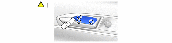
Using moulding remover A, detach the claws and remove the rear door inside handle bezel plug.
4.REMOVE REAR POWER WINDOW REGULATOR SWITCH ASSEMBLY WITH REAR DOOR ARMREST BASE PANEL
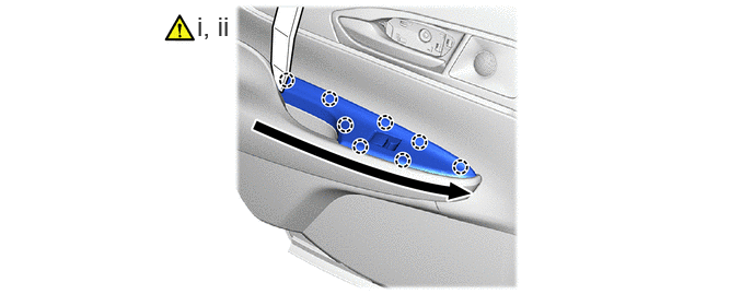

|
Remove in this Order | - | - |
Using moulding remover A, detach the claw and remove the rear power window regulator switch assembly with rear door armrest base panel.
Disconnect the connectors.
67604
5.REMOVE REAR DOOR TRIM BOARD SUB-ASSEMBLY
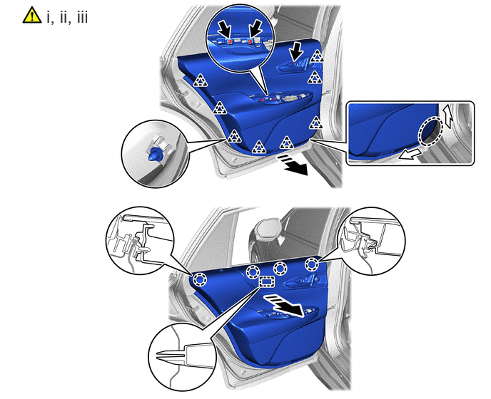

|
Place Hands Here | 
|
Remove in this Direction |
Remove the 3 screws.
Place your hand at the position shown in the illustration, detach the clip.
Pull the rear door trim board sub-assembly shown in the illustration, detach the claws and guides and remove the rear door trim board sub-assembly from the front door panel.
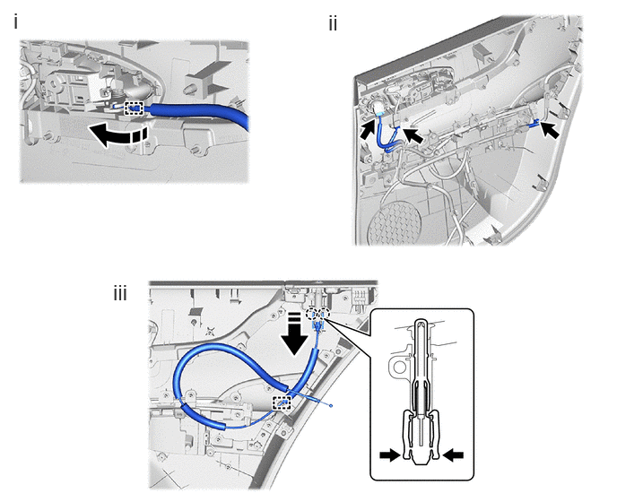
|
|
Remove in this Direction |
|
Push |
Detach the clamps and disconnect the open lever front door lock remote control cable from the rear door inside handle sub-assembly.
Disconnect the connectors.
Detach the claws and clamps, disconnect the lock/unlock knob rear door inside locking cable.
81230
6.REMOVE COURTESY LIGHT ASSEMBLY
81080V
7.REMOVE NO. 2 INTERIOR ILLUMINATION LIGHT ASSEMBLY
69206C
8.REMOVE REAR DOOR INSIDE HANDLE SUB-ASSEMBLY
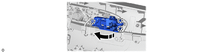
|
|
Remove in this Direction | - | - |
68174A
9.REMOVE REAR DOOR GLASS INNER WEATHERSTRIP
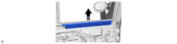
|
|
Remove in this Direction | - | - |
68197A
10.REMOVE REAR DOOR BELT FRONT SEAL
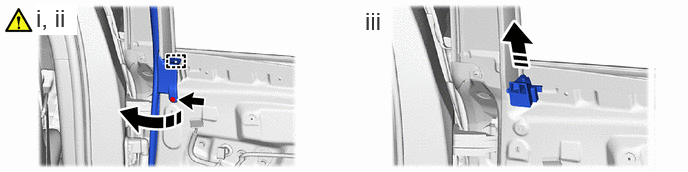
|
|
Remove in this Direction | - | - |
Using a clip remover, detach the clip.
Peel back the rear door belt front seal and disengage the guide as shown in the illustration.
Remove the rear door belt front seal as shown in the illustration.
68199
11.REMOVE REAR DOOR BELT REAR SEAL
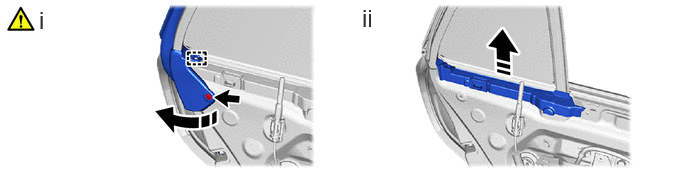
|
|
Remove in this Direction | - | - |
Using a clip remover, detach the clip and turn over the rear door glass weatherstrip inner LH partially.
Remove the rear door belt rear seal as shown in the illustration.
86160B
12.REMOVE REAR SPEAKER ASSEMBLY
89225
13.REMOVE MULTIPLEX NETWORK DOOR REAR ECU (w/ Double Locking System)
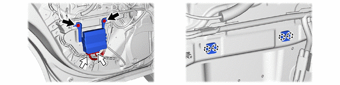
|
|
Screw | 
|
Connector |
67646A
14.REMOVE REAR DOOR ARMREST SET BRACKET
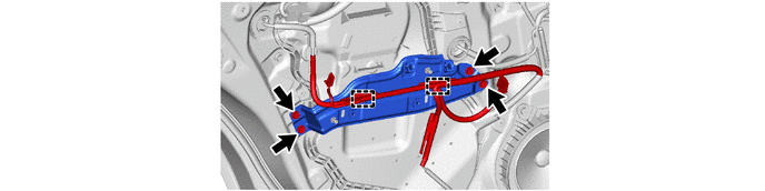
67842E
15.REMOVE REAR DOOR SERVICE HOLE COVER
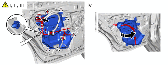

|
Protective Tape | - | - |
Disconnect the connector.
Disconnect the wire harness clamps.
Using a clip remover with its tip wrapped in protective tape, detach the clips.
Remove the lock / unlock knob rear door inside locking cable and open lever rear door lock remote control cable from rear door service hole cover.
16.REMOVE HOLE PLUG
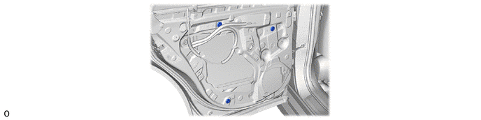
68152C
17.REMOVE REAR DOOR GLASS RUN
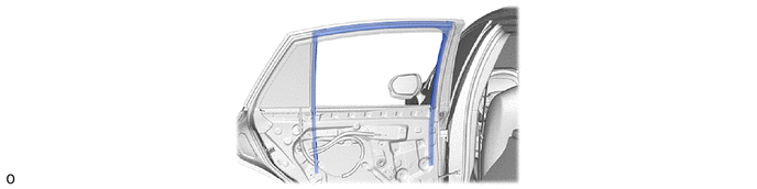
67408E
18.REMOVE REAR DOOR WINDOW DIVISION BAR SUB-ASSEMBLY
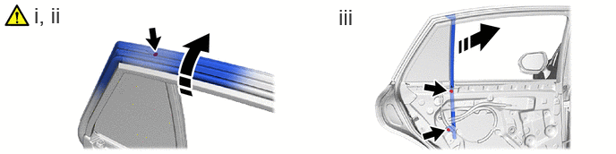
|
|
Remove in this Direction | - | - |
Lift up the rear door weatherstrip as shown in the illustration.
Remove the screws.
Remove the 2 bolts and rear door window division bar sub-assembly.
68124B
19.REMOVE REAR DOOR QUARTER WINDOW GLASS
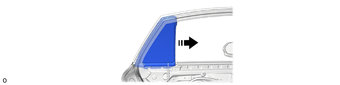
|
|
Remove in this Direction | - | - |
68189
20.REMOVE REAR DOOR QUARTER WINDOW WEATHERSTRIP
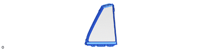
68104
21.REMOVE REAR DOOR GLASS SUB-ASSEMBLY
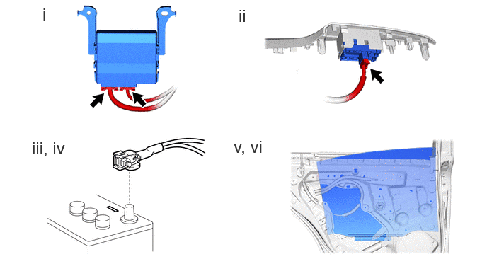
Connect the 2 connectors to the multiplex network door rear ECU.
Connect the connector to the rear power window regulator switch.
Connect the cable to the negative (-) battery terminal.
Turn the ignition switch on.
Move the rear door glass sub-assembly so that the door glass installation position can be seen.
Turn the ignition switch off.
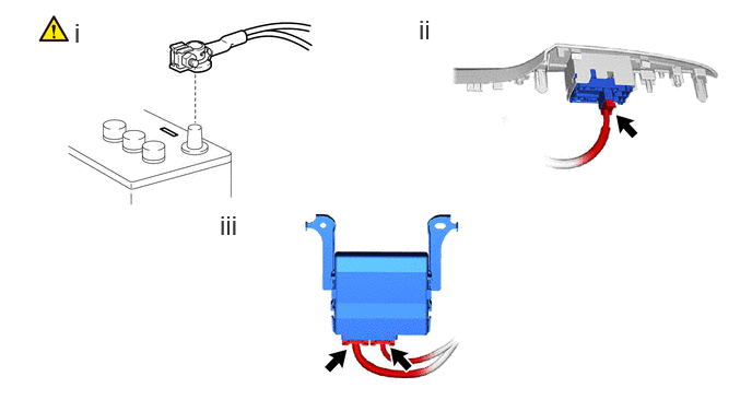
Disconnect the cable from the negative (-) battery terminal.
- CAUTION:
-
- ·
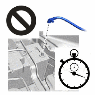
Wait at least 90 seconds after disconnecting the cable from the negative (-) battery terminal to disable the SRS system.
·If an SRS part is accidentally deployed, it may cause a serious injury.
Disconnect the connector from the rear pawer window regulator switch.
Disconnect the 2 connectors from the multiplex network door rear ECU.
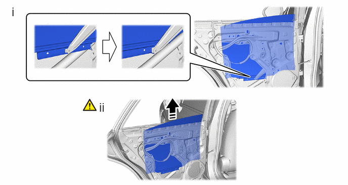
|
|
Remove in this Direction | - | - |
Move the rear door glass sub-assembly and remove the rear door glass sub-assembly.
Remove the rear door glass sub-assembly as shown in the illustration.
- NOTICE:
-
Do not damage the rear door glass.
67674B
22.REMOVE REAR DOOR FRAME GARNISH
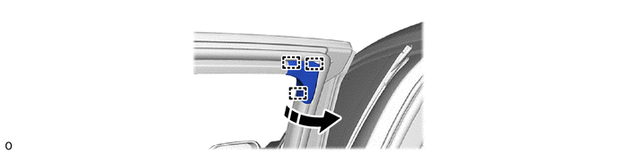
|
|
Remove in this Direction | - | - |
69804
23.REMOVE REAR DOOR WINDOW REGULATOR SUB-ASSEMBLY
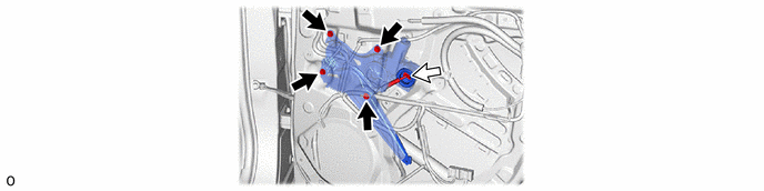
|
|
Bolt |
|
Connector |
69060A
24.REMOVE REAR DOOR WITH MOTOR LOCK ASSEMBLY
|
|
Click here()
|
69038A
25.REMOVE REAR DOOR LOCK COVER SUB-ASSEMBLY
69730M
26.REMOVE OPEN LEVER REAR DOOR LOCK REMOTE CONTROL CABLE
69770E
27.REMOVE LOCK / UNLOCK KNOB REAR DOOR INSIDE LOCKING CABLE
69318D
28.REMOVE DOOR LOCK WIRING HARNESS SEAL
When re-using the rear door lock assembly:
69240
29.REMOVE REAR DOOR OUTSIDE HANDLE ASSEMBLY
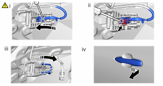
|
|
Remove in this Direction | - | - |
Using a thin-bladed screwdriver with its tip wrapped with protective tape, detach the claws and disconnect the connector cover as shown in the illustration.
Using a thin-bladed screwdriver with its tip wrapped with protective tape, disconnect the connector as shown in the illustration.
Disengage the 2 claws and move the lever as shown in the illustration.
Remove the rear door outside handle assembly as shown in the illustration.
69227L
30.REMOVE REAR DOOR OUTSIDE HANDLE COVER
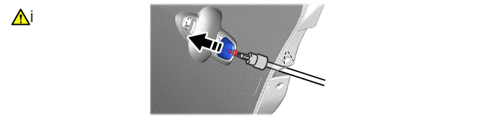
|
|
Remove in this Direction | - | - |
Using a T30 "TORX" socket wrench, loosen the screw to remove the door outside handle cover.
69241G
31.REMOVE REAR DOOR OUTSIDE HANDLE FRONT PAD
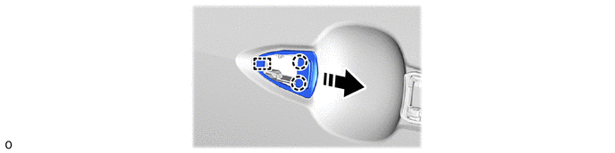
|
|
Remove in this Direction | - | - |
69242G
32.REMOVE REAR DOOR OUTSIDE HANDLE REAR PAD
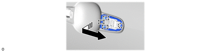
|
|
Remove in this Direction | - | - |
69204A
33.REMOVE REAR DOOR OUTSIDE HANDLE FRAME SUB-ASSEMBLY
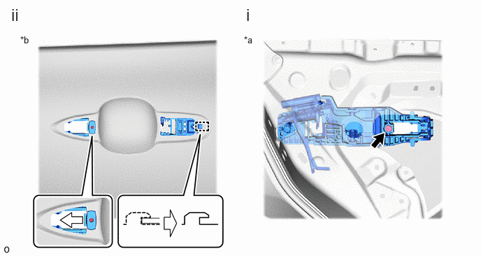
| *a | Inside of the vehicle | *b | Outside of the vehicle |
Using a T30 "TORX" socket wrench, loosen the screw.
Detach the guide and remove the rear door outside handle frame sub-assembly.
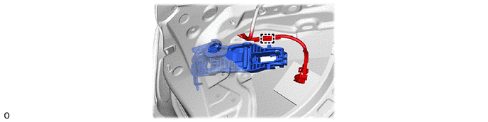
w/ Smart Entry:
1. Disconnect the wire harness clamp.
68640A
34.REMOVE REAR DOOR CHECK ASSEMBLY
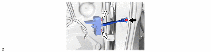
|
|
Nut |
|
Bolt |
67872
35.REMOVE REAR DOOR WEATHERSTRIP
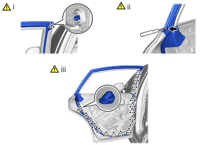
|
|
Protective Tape | - | - |
Using a clip remover with its tip wrapped in protective tape, detach the clips.
Using a clip remover with its tip wrapped in protective tape, detach the clips as shown in the illustration.
Using a clip remover with its tip wrapped in protective tape, detach the clips and remove the rear door weatherstrip.
67874C
36.REMOVE REAR DOOR NO. 5 WEATHERSTRIP
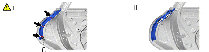
Using a clip remover with its tip wrapped in protective tape, detach the clips.
Heat the rear door No. 5 weatherstrip using a heat light.
- CAUTION:
-
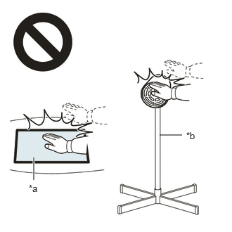 2.365,2 2.698,2 false 0.5,2.333 0.5,2.667 true 0.427,2.708 0.74,2.865 0.313,0.156 10 false *a 2.76,1.927 3.073,2.083 0.313,0.156 10 false *b
*a Heated Part *b Heat Light
- ·
Do not touch the heat light and heated parts.
·Touching the heat light may result in burns.
·Touching heated parts for a long time may result in burns.
- Standard Value:
Part Temperature Rear door No. 5 weatherstrip 20 to 30°C (68 to 86°F)
Remove the double-sided tape and Rear door No. 5 weatherstrip.
75766A
37.REMOVE REAR DOOR REAR WINDOW FRAME MOULDING
|
|
Click here()
|
75762B
38.REMOVE REAR DOOR WINDOW FRAME MOULDING (CENTER PILLAR SIDE)
|
|
Click here()
|
75740
39.REMOVE REAR DOOR BELT MOULDING ASSEMBLY
|
|
Click here()
|
75764A
40.REMOVE REAR DOOR UPPER WINDOW FRAME MOULDING
67896
41.REMOVE REAR DOOR NO. 3 WEATHERSTRIP
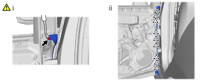
Using a clip remover with its tip wrapped in protective tape, detach the clips.
Remove the clips and front door No. 3 weatherstrip as shown in the illustration.
67888F
42.REMOVE REAR DOOR NO. 2 WEATHERSTRIP
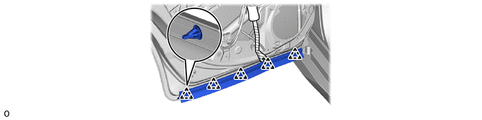
|
|
Protective Tape | - | - |
Using a clip remover with its tip wrapped in protective tape, detach the clips and remove the rear door No.2 weatherstrip LH.
67003C
43.REMOVE REAR DOOR PANEL CUSHION
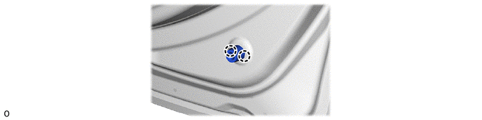
75978H
44.REMOVE REAR DOOR LOWER OUTSIDE STRIPE
|
|
Click here()
|
75988E
45.REMOVE REAR DOOR STRIPE
|
|
Click here()
|
75954A
46.REMOVE REAR INNER BLACK OUT TAPE
|
|
Click here()
|