SEAT FRONT POWER SEAT CONTROL SYSTEM(w/ Memory) Power Seat Position is not Memorized
DESCRIPTION
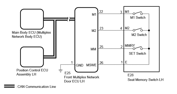
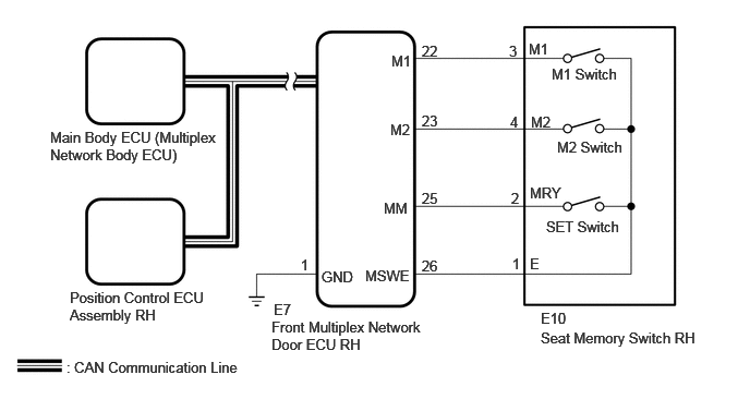
The main body ECU (multiplex network body ECU) will receive the seat memory switch signal from the front multiplex network door ECU LH (for LHD) or RH (for RHD) via CAN communication when either the M1 or M2 switch is pressed while pressing the seat memory SET switch, or when either the M1 or M2 switch is pressed within 3 seconds after pressing the SET switch.
Once the main body ECU (multiplex network body ECU) has received the seat memory switch signal, it will send the store request signal to the position control ECU assembly LH (for LHD) or RH (for RHD) via CAN communication.
WIRING DIAGRAM
for LHD
for RHD
CAUTION / NOTICE / HINT
*1: for LHD
*2: for RHD
- NOTICE:
- ·
The seat position will not be stored if the SET switch and 2 or more of the seat memory switches (for example, M1 switch and M2 switch) are pressed simultaneously.
If a memorizing operation has failed, release all of the switches. The seat memory function will not operate unless the switches are released.
·The seat will not return to the memorized position if 2 or more of the seat memory switches (for example, M1 switch and M2 switch) are pressed simultaneously.
If a restoring operation has failed, release all of the switches. The seat memory restoring function will not operate unless the switches are released.
·The front power seat control system uses the CAN communication system. First, confirm that there are no malfunctions in the CAN communication system. Refer to How to Proceed with Troubleshooting.
·Some parts must be initialized and set when replacing or removing and installing parts.
Click hereGeneral>SETUP>WHEN REPLACING OR REMOVING/INSTALLING PARTS>WORK PROCEDURE
·Initializing the position control ECU assembly LH*1 or RH*2 will clear the seat position memory.
- HINT:
-
Make sure to initialize the position control ECU assembly LH*1 or RH*2 after replacing the seat assembly or any related parts (including removal and installation).
-
Click hereVehicle Interior>SEAT>FRONT POWER SEAT CONTROL SYSTEM (w/ Memory)>REGISTRATION
PROCEDURE
Check the vehicle type.
- Result:
Result Proceed to for LHD A for RHD B
A
B
Check that each function of the power seat operates normally by using the front power seat switch LH.
Click hereVehicle Interior>SEAT>FRONT POWER SEAT CONTROL SYSTEM (w/ Memory)>OPERATION CHECK
- OK:
Each function of the power seat operates normally.
- Result:
Proceed to OK NG
OK
NG
Read the Data List according to the display on the GTS.
- Body Electrical > Front Left Door > Data List
-
Tester Display Measurement Item Range Normal Condition Diagnostic Note Seat Memory Switch1 M1 switch signal ON or OFF ON: M1 switch on
OFF: M1 switch off- Seat Memory Switch2 M2 switch signal ON or OFF ON: M2 switch on
OFF: M2 switch off- Seat Memory Set SW SET switch signal ON or OFF ON: SET switch on
OFF: SET switch off-
- Body Electrical > Front Left Door > Data List
-
Tester Display Seat Memory Switch1 Seat Memory Switch2 Seat Memory Set SW - 50003 225 1,2,4
- OK:
On the GTS screen, ON or OFF is displayed accordingly.
- Result:
Proceed to OK NG
OK
NG
NEXT
Check the seat position memory and restoring functions.
Click hereVehicle Interior>SEAT>FRONT POWER SEAT CONTROL SYSTEM (w/ Memory)>OPERATION CHECK
- OK:
Seat position memory and restoring functions operate normally.
- Result:
Proceed to OK NG
OK
NG
NEXT
Check the seat position memory and restoring functions.
Click hereVehicle Interior>SEAT>FRONT POWER SEAT CONTROL SYSTEM (w/ Memory)>OPERATION CHECK
- OK:
Seat position memory and restoring functions operate normally.
- Result:
Proceed to OK NG
OK
NG
OK
NG
Disconnect the E25 front multiplex network door ECU LH connector.
Disconnect the E28 seat memory switch LH connector.
Measure the resistance according to the value(s) in the table below.
- Standard Resistance:
Tester Connection Condition Specified Condition Click Location & Routing(E25,E28)Location & Routingewd_type=routing;type=c,c;code=E25,E28
Click Connector(E25)Body>Front Door Wire LH / Front Door Wire RH>Front Multiplex Network Door ECU LHewd_type=component;type=c;code=E25;pinno=25,22,23
Click Connector(E28)Body>Front Door Wire LH / Front Door Wire RH>Seat Memory Switch LHewd_type=component;type=c;code=E28;pinno=2,3,4,1
E25-25 (MM) - E28-2 (MMRY) Always Below 1 Ω E25-25 (MM) or E28-2 (MMRY) - Body ground Always 10 kΩ or higher E25-22 (M1) - E28-3 (M1) Always Below 1 Ω E25-22 (M1) or E28-3 (M1) - Body ground Always 10 kΩ or higher E25-23 (M2) - E28-4 (M2) Always Below 1 Ω E25-23 (M2) or E28-4 (M2) - Body ground Always 10 kΩ or higher E28-1 (E) - Body ground Always Below 1 Ω
- Result:
Proceed to OK NG
OK
NG
Check that each function of the power seat operates normally by using the front power seat switch RH.
Click hereVehicle Interior>SEAT>FRONT POWER SEAT CONTROL SYSTEM (w/ Memory)>OPERATION CHECK
- OK:
Each function of the power seat operates normally.
- Result:
Proceed to OK NG
OK
NG
Read the Data List according to the display on the GTS.
- Body Electrical > Front Right Door > Data List
-
Tester Display Measurement Item Range Normal Condition Diagnostic Note Seat Memory Switch1 M1 switch signal ON or OFF ON: M1 switch on
OFF: M1 switch off- Seat Memory Switch2 M2 switch signal ON or OFF ON: M2 switch on
OFF: M2 switch off- Seat Memory Set SW SET switch signal ON or OFF ON: SET switch on
OFF: SET switch off
- Body Electrical > Front Right Door > Data List
-
Tester Display Seat Memory Switch1 Seat Memory Switch2 Seat Memory Set SW - 50003 224 1,2,4
- OK:
On the GTS screen, ON or OFF is displayed accordingly.
- Result:
Proceed to OK NG
OK
NG
NEXT
Check the seat position memory and restoring functions.
Click hereVehicle Interior>SEAT>FRONT POWER SEAT CONTROL SYSTEM (w/ Memory)>OPERATION CHECK
- OK:
Seat position memory and restoring functions operate normally.
- Result:
Proceed to OK NG
OK
NG
NEXT
Check the seat position memory and restoring functions.
Click hereVehicle Interior>SEAT>FRONT POWER SEAT CONTROL SYSTEM (w/ Memory)>OPERATION CHECK
- OK:
Seat position memory and restoring functions operate normally.
- Result:
Proceed to OK NG
OK
NG
OK
NG
Disconnect the E7 front multiplex network door ECU RH connector.
Disconnect the E10 seat memory switch RH connector.
Measure the resistance according to the value(s) in the table below.
- Standard Resistance:
Tester Connection Condition Specified Condition Click Location & Routing(E7,E10)Location & Routingewd_type=routing;type=c,c;code=E7,E10
Click Connector(E7)Body>Front Door Wire LH / Front Door Wire RH>Front Multiplex Network Door ECU RHewd_type=component;type=c;code=E7;pinno=25,22,23
Click Connector(E10)Body>Front Door Wire LH / Front Door Wire RH>Seat Memory Switch RHewd_type=component;type=c;code=E10;pinno=2,3,4,1
E7-25 (MM) - E10-2 (MMRY) Always Below 1 Ω E7-25 (MM) or E10-2 (MMRY) - Body ground Always 10 kΩ or higher E7-22 (M1) - E10-3 (M1) Always Below 1 Ω E7-22 (M1) or E10-3 (M1) - Body ground Always 10 kΩ or higher E7-23 (M2) - E10-4 (M2) Always Below 1 Ω E7-23 (M2) or E10-4 (M2) - Body ground Always 10 kΩ or higher E10-1 (E) - Body ground Always Below 1 Ω
- Result:
Proceed to OK NG
OK
NG