HYBRID / BATTERY CONTROL BATTERY VOLTAGE SENSOR INSTALLATION
CAUTION / NOTICE / HINT
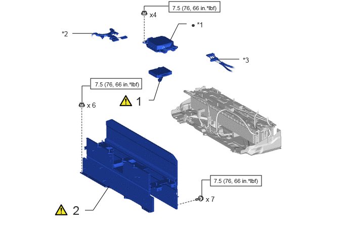
| Procedure | Part Name Code | 
|

|

|
|
|---|---|---|---|---|---|
| 1 | BATTERY VOLTAGE SENSOR (for Lower Side) | 89892A | ( ) |
- | - |
| 2 | UPPER EV BATTERY CARRIER SUB-ASSEMBLY | - | ()
|
- | - |
| *1 | NO. 1 EV BATTERY PROTECTOR (for Lower Side) | *2 | WIRE HARNESS (NO. 2 EV SUPPLY STACK SUB-ASSEMBLY) CELL VOLTAGE DETECTION CIRCUIT |
| *3 | NO. 1 EV BATTERY PACK WIRE | - | - |

|
N*m (kgf*cm, ft.*lbf): Specified torque | ● | Non-reusable part |
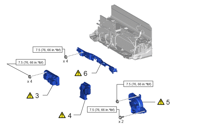
| Procedure | Part Name Code |
|
|
|
|
|---|---|---|---|---|---|
| 3 | NO. 1 EV BATTERY JUNCTION BLOCK ASSEMBLY | G92Z0A | ()
|
- | - |
| 4 | NO. 6 EV BATTERY INTAKE DUCT | G92D6A | ()
|
- | - |
| 5 | BATTERY COOLING BLOWER ASSEMBLY WITH NO. 5 EV BATTERY INTAKE DUCT | - | ()
|
- | - |
| 6 | WIRE HARNESS CLAMP BRACKET | - | ()
|
- | - |
|
|
N*m (kgf*cm, ft.*lbf): Specified torque | - | - |
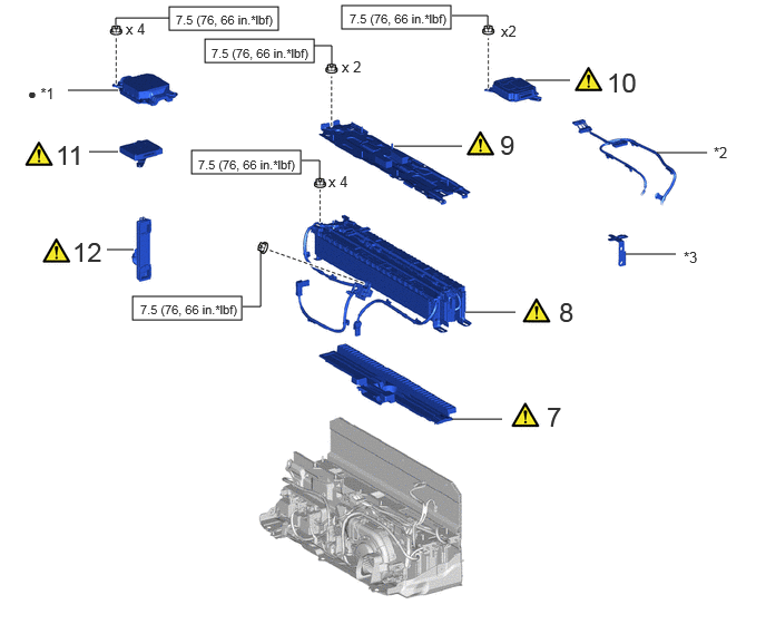
| Procedure | Part Name Code |
|
|
|
|
|---|---|---|---|---|---|
| 7 | NO. 8 EV BATTERY INTAKE DUCT | G92D8A | ()
|
- | - |
| 8 | NO. 1 EV SUPPLY STACK SUB-ASSEMBLY | G9508A | ()
|
- | - |
| 9 | NO. 7 EV BATTERY SHIELD SUB-ASSEMBLY (for Upper Side) | G920WA | ()
|
- | - |
| 10 | BATTERY ECU ASSEMBLY | 89890A | ()
|
- | - |
| 11 | BATTERY VOLTAGE SENSOR (for Upper Side) | 89892A | ()
|
- | - |
| 12 | NO. 1 EV BATTERY EXHAUST DUCT | G92F1A | ()
|
- | - |
| *1 | NO. 1 EV BATTERY PROTECTOR (for Upper Side) | *2 | NO. 1 EV BATTERY PACK WIRE |
| *3 | WIRE HARNESS CLAMP BRACKET | - | - |
|
|
N*m (kgf*cm, ft.*lbf): Specified torque | ● | Non-reusable part |
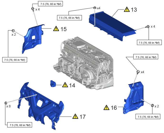
| Procedure | Part Name Code |
|
|
|
|
|---|---|---|---|---|---|
| 13 | UPPER NO. 1 EV BATTERY COVER SUB-ASSEMBLY | G920LC | ()
|
- | - |
| 14 | EV BATTERY TERMINAL BLOCK | G92Z2A | ()
|
- | - |
| 15 | NO. 1 EV BATTERY SHIELD SUB-ASSEMBLY | G920QB | ()
|
- | - |
| 16 | NO. 2 EV BATTERY SHIELD SUB-ASSEMBLY | G920RB | ()
|
- | - |
| 17 | UPPER EV BATTERY COVER PANEL | G92N1B | ()
|
- | - |
|
|
N*m (kgf*cm, ft.*lbf): Specified torque | - | - |
| Procedure | Part Name Code |
|
|
|
|
|---|---|---|---|---|---|
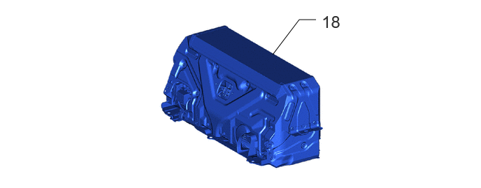
| 18 | EV SUPPLY BATTERY ASSEMBLY | G9510B | - | - | - |
| Procedure | Part Name Code |
|
|
|
|
|---|---|---|---|---|---|
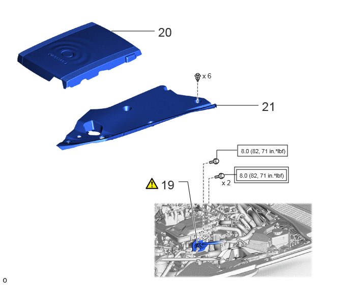
| 19 | FC CONVERTER POWER OUTLET CABLE (INVERTER WITH CONVERTER ASSEMBLY) | G9200A | ()
|
- | - |
| 20 | FC STACK COVER SUB-ASSEMBLY | 1A906 | - | - | - |
| 21 | UPPER RADIATOR SUPPORT SEAL | 53292A | - | - | - |

|
Tightening torque for "Major areas involving basic vehicle performance such as moving/turning/stopping": N*m (kgf*cm, ft.*lbf) |
|
N*m (kgf*cm, ft.*lbf): Specified torque |
| Procedure | Part Name Code |
|
|
|
|
|---|---|---|---|---|---|
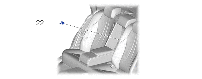
| 22 | SERVICE PLUG GRIP | G3834 | - | - | - |
PROCEDURE

 89892A
1.INSTALL BATTERY VOLTAGE SENSOR (for Lower Side)
|
|
|
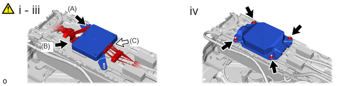
Install the battery voltage sensor (for lower side).
- NOTICE:
- ·
Do not drop the battery voltage sensor (for lower side), strike it with tools or subject it to impact.
·If the battery voltage sensor (for lower side) is subjected to an impact, replace it with a new one.
Connect connector C on the No. 1 EV battery pack wire side.
- CAUTION:
-
Make sure to connect connector C on the No. 1 EV battery pack wire side first.
- NOTICE:
-
Make sure that the connector is connected securely.
Connect connector A and connector B to the wire harness (No. 2 EV supply stack sub-assembly) cell voltage detection circuit.
- CAUTION:
-
Make sure to connect connector C on the No. 1 EV battery pack wire side first.
- NOTICE:
-
Make sure that the connector is connected securely.
Install a new No. 1 EV battery protector (for lower side) with the 4 nuts.
- Torque:
- 7.5 N*m (76 kgf*cm, 66 in.*lbf)
2.INSTALL UPPER EV BATTERY CARRIER SUB-ASSEMBLY
|
|
Click here()
|
G92Z0A
3.INSTALL NO. 1 EV BATTERY JUNCTION BLOCK ASSEMBLY
|
|
Click here()
|
G92D6A
4.INSTALL NO. 6 EV BATTERY INTAKE DUCT
|
|
Click here()
|
5.INSTALL BATTERY COOLING BLOWER ASSEMBLY WITH NO. 5 EV BATTERY INTAKE DUCT
|
|
Click here()
|
6.INSTALL WIRE HARNESS CLAMP BRACKET
|
|
Click here()
|
G92D8A
7.INSTALL NO. 8 EV BATTERY INTAKE DUCT
|
|
Click here()
|
G9508A
8.INSTALL NO. 1 EV SUPPLY STACK SUB-ASSEMBLY
|
|
Click here()
|
G920WA
9.INSTALL NO. 7 EV BATTERY SHIELD SUB-ASSEMBLY (for Upper Side)
|
|
Click here()
|
89890A
10.INSTALL BATTERY ECU ASSEMBLY
|
|
Click here()
|
89892A
11.INSTALL BATTERY VOLTAGE SENSOR (for Upper Side)
|
|
|
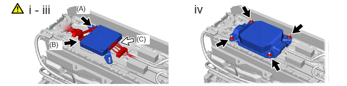
Install the battery voltage sensor (for upper side).
- NOTICE:
- ·
Do not drop the battery voltage sensor (for upper side), strike it with tools or subject it to impact.
·If the battery voltage sensor (for upper side) is subjected to an impact, replace it with a new one.
Connect connector C on the No. 1 EV battery pack wire side.
- CAUTION:
-
Make sure to connect connector C on the No. 1 EV battery pack wire side first.
- NOTICE:
-
Make sure that the connector is connected securely.
Connect connector A and connector B to the wire harness (No. 1 EV supply stack sub-assembly) cell voltage detection circuit.
- CAUTION:
-
Make sure to connect connector C on the No. 1 EV battery pack wire side first.
- NOTICE:
-
Make sure that the connector is connected securely.
Install a new No. 1 EV battery protector (for upper side) with the 4 nuts.
- Torque:
- 7.5 N*m (76 kgf*cm, 66 in.*lbf)
G92F1A
12.INSTALL NO. 1 EV BATTERY EXHAUST DUCT
|
|
Click here()
|
G920LC
13.INSTALL UPPER NO. 1 EV BATTERY COVER SUB-ASSEMBLY
|
|
Click here()
|
G92Z2A
14.INSTALL EV BATTERY TERMINAL BLOCK
|
|
Click here()
|
G920QB
15.INSTALL NO. 1 EV BATTERY SHIELD SUB-ASSEMBLY
|
|
Click here()
|
G920RB
16.INSTALL NO. 2 EV BATTERY SHIELD SUB-ASSEMBLY
|
|
Click here()
|
G92N1B
17.INSTALL UPPER EV BATTERY COVER PANEL
|
|
Click here()
|
G9510B
18.INSTALL EV SUPPLY BATTERY ASSEMBLY
G9200A
19.CONNECT FC CONVERTER POWER OUTLET CABLE (INVERTER WITH CONVERTER ASSEMBLY)
|
|
Click here()
|
1A906
20.INSTALL FC STACK COVER SUB-ASSEMBLY
53292A
21.INSTALL UPPER RADIATOR SUPPORT SEAL
G3834
22.INSTALL SERVICE PLUG GRIP