HYBRID / BATTERY CONTROL HV BATTERY STACK INSTALLATION
CAUTION / NOTICE / HINT
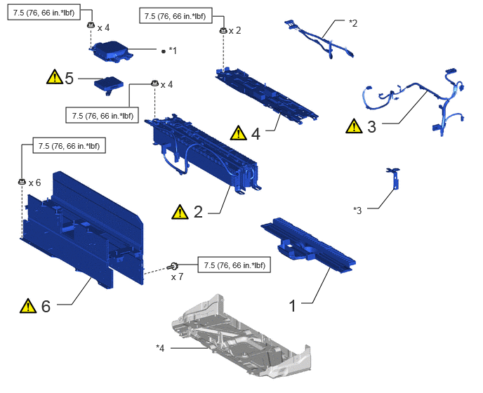
| Procedure | Part Name Code | 
|

|

|
|
|---|---|---|---|---|---|
| 1 | NO. 9 EV BATTERY INTAKE DUCT | G92D9A | - | - | - |
| 2 | NO. 2 EV SUPPLY STACK SUB-ASSEMBLY | G9509A | ( ) |
- | - |
| 3 | NO. 2 EV BATTERY PACK WIRE | G92X2A | ()
|
- | - |
| 4 | NO. 7 EV BATTERY SHIELD SUB-ASSEMBLY (for Lower Side) | G920WA | ()
|
- | - |
| 5 | BATTERY VOLTAGE SENSOR (for Lower Side) | 89892A | ()
|
- | - |
| 6 | UPPER EV BATTERY CARRIER SUB-ASSEMBLY | - | ()
|
- | - |
| *1 | NO. 1 EV BATTERY PROTECTOR (for Lower Side) | *2 | NO. 1 EV BATTERY PACK WIRE |
| *3 | WIRE HARNESS (NO. 2 EV SUPPLY STACK SUB-ASSEMBLY) CELL VOLTAGE DETECTION CIRCUIT | *4 | LOWER EV BATTERY CARRIER SUBASSEMBLY |

|
N*m (kgf*cm, ft.*lbf): Specified torque | ● | Non-reusable part |
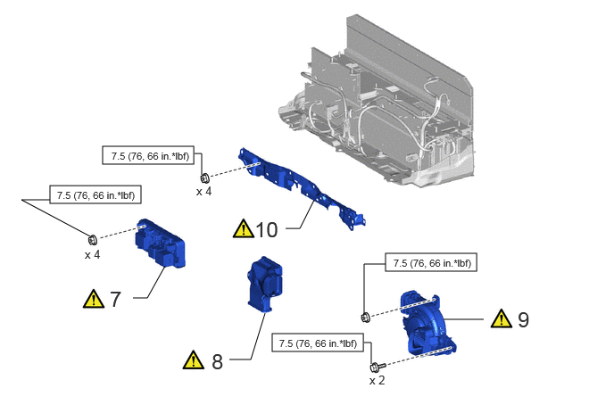
| Procedure | Part Name Code |
|
|
|
|
|---|---|---|---|---|---|
| 7 | NO. 1 EV BATTERY JUNCTION BLOCK ASSEMBLY | G92Z0A | ()
|
- | - |
| 8 | NO. 6 EV BATTERY INTAKE DUCT | G92D6A | ()
|
- | - |
| 9 | BATTERY COOLING BLOWER ASSEMBLY WITH NO. 5 EV BATTERY INTAKE DUCT | - | ()
|
- | - |
| 10 | WIRE HARNESS CLAMP BRACKET | - | ()
|
||
|
|
N*m (kgf*cm, ft.*lbf): Specified torque | - | - |
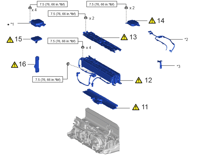
| Procedure | Part Name Code |
|
|
|
|
|---|---|---|---|---|---|
| 11 | NO. 8 EV BATTERY INTAKE DUCT | G92D8A | ()
|
- | - |
| 12 | NO. 1 EV SUPPLY STACK SUB-ASSEMBLY | G9508A | ()
|
- | - |
| 13 | NO. 7 EV BATTERY SHIELD SUB-ASSEMBLY (for Upper Side) | G920WA | ()
|
- | - |
| 14 | BATTERY ECU ASSEMBLY | 89890A | ()
|
- | - |
| 15 | BATTERY VOLTAGE SENSOR (for Upper Side) | 89892A | ()
|
- | - |
| 16 | NO. 1 EV BATTERY EXHAUST DUCT | G92F1A | ()
|
- | - |
| *1 | NO. 1 EV BATTERY PROTECTOR | *2 | NO. 2 EV BATTERY PACK WIRE |
| *3 | WIRE HARNESS CLAMP BRACKET | - | - |
|
|
N*m (kgf*cm, ft.*lbf): Specified torque | ● | Non-reusable part |
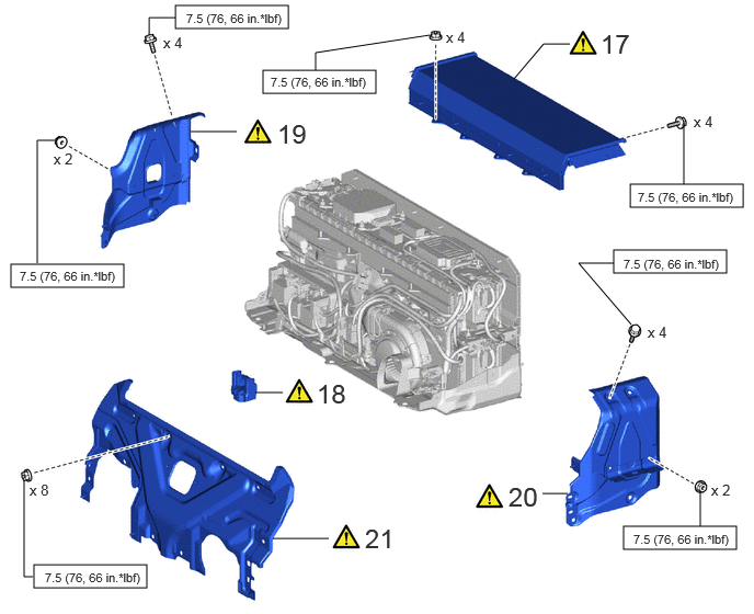
| Procedure | Part Name Code |
|
|
|
|
|---|---|---|---|---|---|
| 17 | UPPER NO. 1 EV BATTERY COVER SUB-ASSEMBLY | G920LC | ()
|
- | - |
| 18 | EV BATTERY TERMINAL BLOCK | G92Z2A | ()
|
- | - |
| 19 | NO. 1 EV BATTERY SHIELD SUB-ASSEMBLY | G920QB | ()
|
- | - |
| 20 | NO. 2 EV BATTERY SHIELD SUB-ASSEMBLY | G920RB | ()
|
- | - |
| 21 | UPPER EV BATTERY COVER PANEL | G92N1B | ()
|
- | - |
|
|
N*m (kgf*cm, ft.*lbf): Specified torque | - | - |
| Procedure | Part Name Code |
|
|
|
|
|---|---|---|---|---|---|
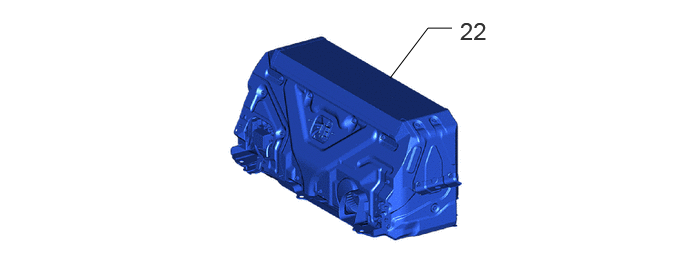
| 22 | EV SUPPLY BATTERY ASSEMBLY | G9510B | - | - | - |
| Procedure | Part Name Code |
|
|
|
|
|---|---|---|---|---|---|
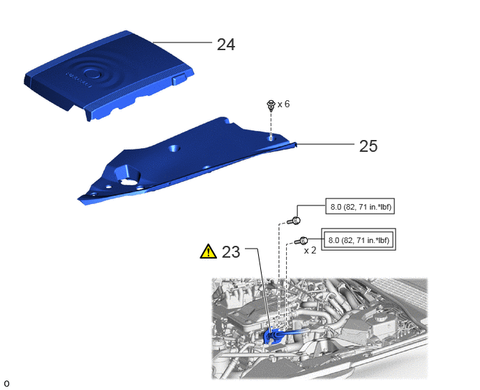
| 23 | FC CONVERTER POWER OUTLET CABLE (INVERTER WITH CONVERTER ASSEMBLY) | G9200A | ()
|
- | - |
| 24 | FC STACK COVER SUB-ASSEMBLY | 1A906 | - | - | - |
| 25 | UPPER RADIATOR SUPPORT SEAL | 53292A | - | - | - |

|
Tightening torque for "Major areas involving basic vehicle performance such as moving/turning/stopping": N*m (kgf*cm, ft.*lbf) |
|
N*m (kgf*cm, ft.*lbf): Specified torque |
| Procedure | Part Name Code |
|
|
|
|
|---|---|---|---|---|---|
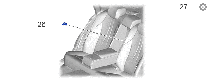
| 26 | SERVICE PLUG GRIP | G3834 | - | - | - |
| 27 | PERFORM UTILITY | - | - | - | ()
|
PROCEDURE

 G92D9A
1.INSTALL NO. 9 EV BATTERY INTAKE DUCT
G9509A
2.INSTALL NO. 2 EV SUPPLY STACK SUB-ASSEMBLY
|
|
|
- Torque:
- 7.5 N*m (76 kgf*cm, 66 in.*lbf)
G92X2A
3.INSTALL NO. 2 EV BATTERY PACK WIRE
|
|
|
G920WA
4.INSTALL NO. 7 EV BATTERY SHIELD SUB-ASSEMBLY (for Lower Side)
|
|
|
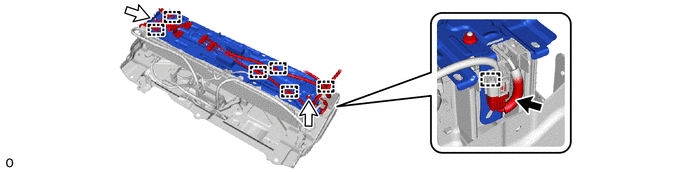
- Torque:
- 7.5 N*m (76 kgf*cm, 66 in.*lbf)
89892A
5.INSTALL BATTERY VOLTAGE SENSOR (for Lower Side)
|
|
Click here()
|
6.INSTALL UPPER EV BATTERY CARRIER SUB-ASSEMBLY
|
|
|
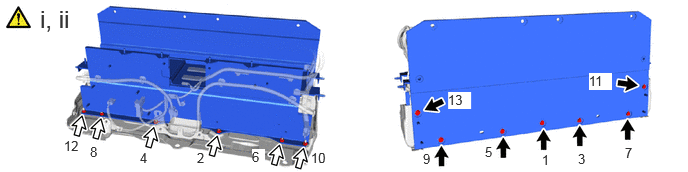
Install the upper EV battery carrier sub-assembly.
While pressing the upper EV battery carrier sub-assembly downwards, tighten the 7 bolts and 6 nuts in the order shown in the illustration.
- Torque:
- 7.5 N*m (76 kgf*cm, 66 in.*lbf)
- NOTICE:
-
After installing, check that the upper EV battery carrier sub-assembly is properly installed.
- HINT:
- ·
An elastic body for resonance countermeasures with the No. 2 EV supply stack sub-assembly exists in the center of the No. 7 EV battery shield sub-assembly and generates a reactive force by being squashed by the upper EV battery carrier sub-assembly.
·Install the upper EV battery carrier sub-assembly while pressing downwards with 475 to 517 N (48 to 53 kgf, 106.8 to 116.2 lbf).
G92Z0A
7.INSTALL NO. 1 EV BATTERY JUNCTION BLOCK ASSEMBLY
|
|
|
- Torque:
- 7.5 N*m (76 kgf*cm, 66 in.*lbf)
G92D6A
8.INSTALL NO. 6 EV BATTERY INTAKE DUCT
|
|
|
9.INSTALL BATTERY COOLING BLOWER ASSEMBLY WITH NO. 5 EV BATTERY INTAKE DUCT
|
|
|
- Torque:
- 7.5 N*m (76 kgf*cm, 66 in.*lbf)
10.INSTALL WIRE HARNESS CLAMP BRACKET
|
|
|
- Torque:
- 7.5 N*m (76 kgf*cm, 66 in.*lbf)
G92D8A
11.INSTALL NO. 8 EV BATTERY INTAKE DUCT
|
|
|
G9508A
12.INSTALL NO. 1 EV SUPPLY STACK SUB-ASSEMBLY
|
|
|
- Torque:
- 7.5 N*m (76 kgf*cm, 66 in.*lbf)
G920WA
13.INSTALL NO. 7 EV BATTERY SHIELD SUB-ASSEMBLY (for Upper Side)
|
|
|
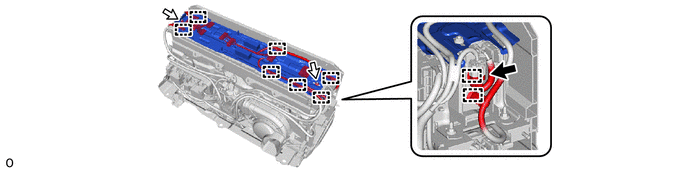
- Torque:
- 7.5 N*m (76 kgf*cm, 66 in.*lbf)
89890A
14.INSTALL BATTERY ECU ASSEMBLY
|
|
Click here()
|
89892A
15.INSTALL BATTERY VOLTAGE SENSOR (for Upper Side)
|
|
Click here()
|
G92F1A
16.INSTALL NO. 1 EV BATTERY EXHAUST DUCT
|
|
|
G920LC
17.INSTALL UPPER NO. 1 EV BATTERY COVER SUB-ASSEMBLY
|
|
|
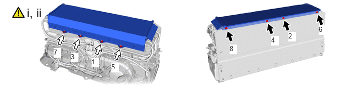
Install the upper No. 1 EV battery cover sub-assembly.
While pressing the upper No. 1 EV battery cover sub-assembly downwards, tighten the 4 bolts and 4 nuts in the order shown in the illustration.
- Torque:
- 7.5 N*m (76 kgf*cm, 66 in.*lbf)
- NOTICE:
-
After installing, check that the upper No. 1 EV battery cover sub-assembly is properly installed.
- HINT:
- ·
An elastic body for resonance countermeasures with the No. 1 EV supply stack sub-assembly exists in the center of the No. 7 EV battery shield sub-assembly and generates a reactive force by being squashed by the upper No. 1 EV battery cover sub-assembly.
·Install the upper No. 1 EV battery cover sub-assembly while pressing downwards with 426 N (43 kgf, 95.8 lbf) or more.
G92Z2A
18.INSTALL EV BATTERY TERMINAL BLOCK
|
|
Click here()
|
G920QB
19.INSTALL NO. 1 EV BATTERY SHIELD SUB-ASSEMBLY
|
|
|
- Torque:
- 7.5 N*m (76 kgf*cm, 66 in.*lbf)
G920RB
20.INSTALL NO. 2 EV BATTERY SHIELD SUB-ASSEMBLY
|
|
|
- Torque:
- 7.5 N*m (76 kgf*cm, 66 in.*lbf)
G92N1B
21.INSTALL UPPER EV BATTERY COVER PANEL
|
|
|
- Torque:
- 7.5 N*m (76 kgf*cm, 66 in.*lbf)
G9510B
22.INSTALL EV SUPPLY BATTERY ASSEMBLY
G9200A
23.CONNECT FC CONVERTER POWER OUTLET CABLE (INVERTER WITH CONVERTER ASSEMBLY)
|
|
Click here()
|
1A906
24.INSTALL FC STACK COVER SUB-ASSEMBLY
53292A
25.INSTALL UPPER RADIATOR SUPPORT SEAL
G3834
26.INSTALL SERVICE PLUG GRIP
27. PERFORM UTILITY
|
|
|