HYBRID / BATTERY CONTROL INVERTER WITH CONVERTER INSTALLATION
CAUTION / NOTICE / HINT
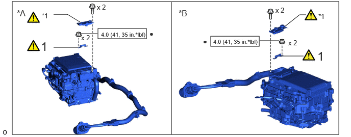
| Procedure | Part Name Code | 
|

|

|
|
|---|---|---|---|---|---|
| 1 | HIGH VOLTAGE FUSE | - | ( ) |
- | - |
| *A | for LHD | *A | for RHD |
| *1 | CONNECTOR COVER ASSEMBLY | - | - |

|
N*m (kgf*cm, ft.*lbf): Specified torque | ● | Non-reusable part |
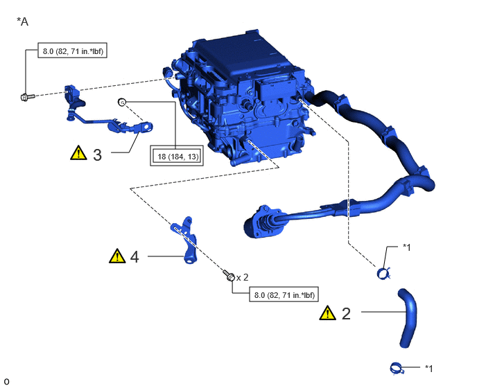
| Procedure | Part Name Code |
|
|
|
|
|---|---|---|---|---|---|
| 2 | NO. 1 INVERTER COOLING HOSE | - | ()
|
- | - |
| 3 | INVERTER BUS-BAR PLATE SUB-ASSEMBLY | G9205A | ()
|
- | - |
| 4 | NO. 4 INVERTER BRACKET | G9217A | ()
|
- | - |
| *A | for LHD | - | - |
| *1 | HOSE CLIP | - | - |

|
Tightening torque for "Major areas involving basic vehicle performance such as moving/turning/stopping": N*m (kgf*cm, ft.*lbf) |
|
N*m (kgf*cm, ft.*lbf): Specified torque |
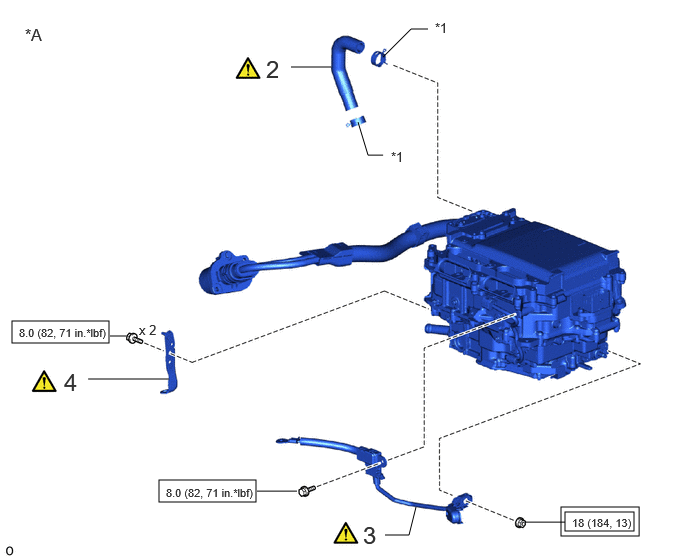
| Procedure | Part Name Code |
|
|
|
|
|---|---|---|---|---|---|
| 2 | NO. 1 INVERTER COOLING HOSE | - | ()
|
- | - |
| 3 | INVERTER BUS-BAR PLATE SUB-ASSEMBLY | G9205A | ()
|
- | - |
| 4 | NO. 4 INVERTER BRACKET | G9217A | ()
|
- | - |
| *A | for RHD | - | - |
| *1 | HOSE CLIP | - | - |
|
|
Tightening torque for "Major areas involving basic vehicle performance such as moving/turning/stopping": N*m (kgf*cm, ft.*lbf) |
|
N*m (kgf*cm, ft.*lbf): Specified torque |
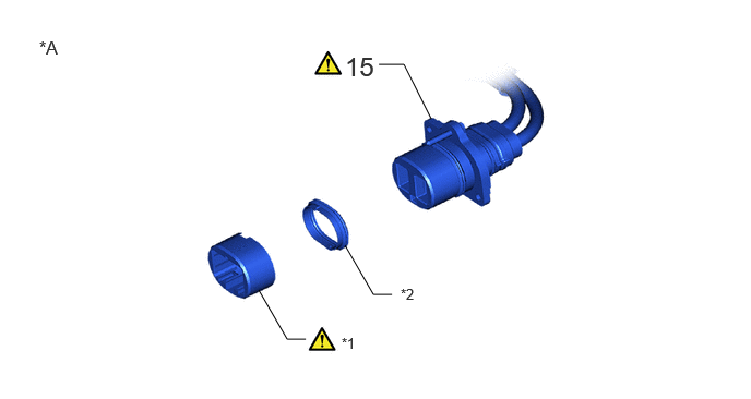
| Procedure | Part Name Code |
|
|
|
|
|---|---|---|---|---|---|
| 15 | FC CONVERTER POWER OUTLET CABLE (INVERTER WITH CONVERTER ASSEMBLY) | G9200A | ()
|
- | - |
| *A | If the FC converter power outlet front holder and FC converter power outlet front gasket are left in the stack, remove them using the following procedure | - | - |
| *1 | FC CONVERTER POWER OUTLET FRONT HOLDER | *2 | FC CONVERTER POWER OUTLET FRONT GASKET |
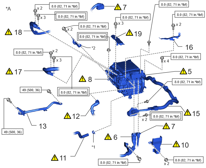
| Procedure | Part Name Code |
|
|
|
|
|---|---|---|---|---|---|
| 5 | INVERTER WITH CONVERTER ASSEMBLY | G9200A | ()
|
- | - |
| 6 | FC JUNCTION CABLE | G9A2C | ()
|
- | - |
| 7 | FRONT COMPARTMENT MAIN WIRE | 82111C | ()
|
- | - |
| 8 | INVERTER BUS-BAR PLATE SUB-ASSEMBLY | G9205A | ()
|
- | - |
| 10 | WIRE HARNESS CLAMP BRACKET | - | - | - | - |
| 11 | NO. 3 FC INVERTER COOLING HOSE | G91C3 | ()
|
- | - |
| 12 | NO. 1 FC INVERTER COOLING HOSE SUB-ASSEMBLY | G90A1 | ()
|
- | - |
| 13 | FENDER APRON BRACE SUB-ASSEMBLY RH | 53705F | - | - | - |
| 15 | FC CONVERTER POWER OUTLET CABLE (INVERTER WITH CONVERTER ASSEMBLY) | G9200A | ()
|
- | - |
| 16 | INVERTER MOTOR CABLE BRACKET ASSEMBLY | G1240C | - | - | - |
| 17 | NO. 2 BATTERY PACK WIRE | 821H3B | ()
|
- | - |
| 18 | FC AIR COMPRESSOR MOTOR CABLE ASSEMBLY | 17A90 | ()
|
- | - |
| 19 | INVERTER TERMINAL COVER | G9223B | ()
|
- | - |
| *A | for LHD | - | - |
| *1 | HOSE CLIP | *2 | NO. 6 INVERTER BRACKET |
|
|
Tightening torque for "Major areas involving basic vehicle performance such as moving/turning/stopping": N*m (kgf*cm, ft.*lbf) |
|
N*m (kgf*cm, ft.*lbf): Specified torque |
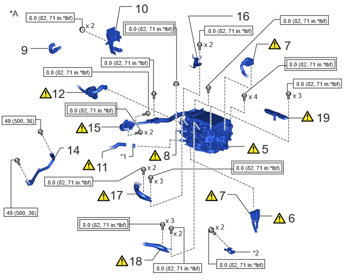
| Procedure | Part Name Code |
|
|
|
|
|---|---|---|---|---|---|
| 5 | INVERTER WITH CONVERTER ASSEMBLY | G9200A | ()
|
- | - |
| 6 | FC JUNCTION CABLE | G9A2C | ()
|
- | - |
| 7 | FRONT COMPARTMENT MAIN WIRE | 82111C | ()
|
- | - |
| 8 | INVERTER BUS-BAR PLATE SUB-ASSEMBLY | G9205A | ()
|
- | - |
| 9 | WATER HOSE SUB-ASSEMBLY C | 87209C | - | - | - |
| 10 | WIRE HARNESS CLAMP BRACKET | - | - | - | - |
| 11 | NO. 3 FC INVERTER COOLING HOSE | G91C3 | ()
|
- | - |
| 12 | NO. 1 FC INVERTER COOLING HOSE SUB-ASSEMBLY | G90A1 | ()
|
- | - |
| 14 | FENDER APRON BRACE SUB-ASSEMBLY LH | 53706A | - | - | - |
| 15 | FC CONVERTER POWER OUTLET CABLE (INVERTER WITH CONVERTER ASSEMBLY) | G9200A | ()
|
- | - |
| 16 | INVERTER MOTOR CABLE BRACKET ASSEMBLY | G1240C | - | - | - |
| 17 | NO. 2 BATTERY PACK WIRE | 821H3B | ()
|
- | - |
| 18 | FC AIR COMPRESSOR MOTOR CABLE ASSEMBLY | 17A90 | ()
|
- | - |
| 19 | INVERTER TERMINAL COVER | G9223B | ()
|
- | - |
| *A | for RHD | - | - |
| *1 | HOSE CLIP | *2 | NO. 6 INVERTER BRACKET |
|
|
Tightening torque for "Major areas involving basic vehicle performance such as moving/turning/stopping": N*m (kgf*cm, ft.*lbf) |
|
N*m (kgf*cm, ft.*lbf): Specified torque |
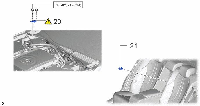
| Procedure | Part Name Code |
|
|
|
|
|---|---|---|---|---|---|
| 20 | INSTALL CONNECTOR COVER ASSEMBLY | - | ()
|
- | - |
| 21 | SERVICE PLUG GRIP | G3834 | - | - | - |
|
|
N*m (kgf*cm, ft.*lbf): Specified torque | - | - |
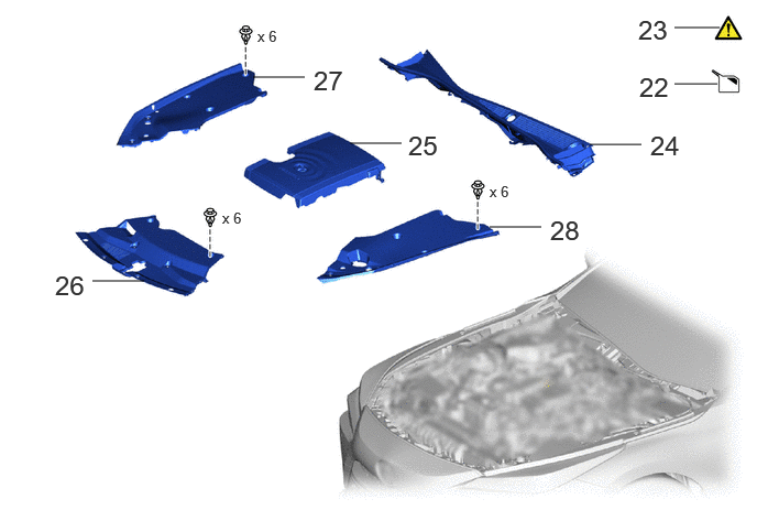
| Procedure | Part Name Code |
|
|
|
|
|---|---|---|---|---|---|
| 22 | ADD COOLANT (for Inverter) | - | - | ()
|
- |
| 23 | INSPECT FOR COOLANT LEAK (for Inverter) | - | ()
|
- | - |
| 24 | COWL TOP VENTILATOR LOUVER SUB-ASSEMBLY | 55708 | - | - | - |
| 25 | FC STACK COVER SUB-ASSEMBLY | 1A906 | - | - | - |
| 26 | LOWER RADIATOR AIR DEFLECTOR | 53295 | - | - | - |
| 27 | RADIATOR COVER PLATE | 53291B | - | - | - |
| 28 | UPPER RADIATOR SUPPORT SEAL | 53292A | - | - | - |
PROCEDURE

 1.INSTALL HIGH VOLTAGE FUSE
|
|
|
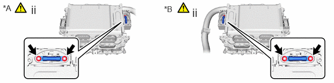
Remove the connector cover assembly.
Click hereEngine / Hybrid System>HYBRID / BATTERY CONTROL>INVERTER WITH CONVERTER>REMOVAL
Install the high voltage fuse with the 2 new nuts.
- Torque:
- 4.0 N*m (41 kgf*cm, 35 in.*lbf)
- NOTICE:
-
Be sure to use a torque wrench to tighten the nuts.
Temporarily install the connector cover assembly.
Click hereEngine / Hybrid System>HYBRID / BATTERY CONTROL>INVERTER WITH CONVERTER>REMOVAL
2.INSTALL NO. 1 INVERTER COOLING HOSE
|
|
|
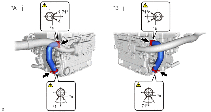
| *A | for LHD | *B | for RHD |
| *a | Alignment Mark | - | - |
Install the No. 1 inverter cooling hose to the inverter with converter assembly and slide the 2 hose clips to secure it.
- HINT:
-
Make sure that the 2 hose clips are positioned as shown in the illustration.
G9205A
3.INSTALL INVERTER BUS-BAR PLATE SUB-ASSEMBLY
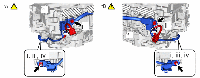
| *A | for LHD | *B | for RHD |
| *a | Stopper | - | - |
Temporarily install the inverter bus-bar plate sub-assembly with the nut by tightening the nut 3 or more revolutions.
- NOTICE:
-
If the inverter bus-bar plate sub-assembly is dropped or deformed, replace it with a new one.
- HINT:
-
When installing, align with the stopper.
Install the bolt and engage the clamp.
- Torque:
- 8.0 N*m (82 kgf*cm, 71 in.*lbf)
Tighten the nut.
- Torque:
- 18 N*m (184 kgf*cm, 13 ft.*lbf)
Close the terminal cover.
G9217A
4.INSTALL NO. 4 INVERTER BRACKET
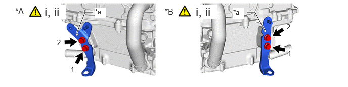
| *A | for LHD | *B | for RHD |
| *a | Stopper | - | - |
Temporarily install the No. 4 inverter bracket to the inverter with converter assembly with the 2 bolts.
- HINT:
-
When installing, align with the stopper.
Tighten the 2 bolts in the sequence shown in the illustration.
- Torque:
- 8.0 N*m (82 kgf*cm, 71 in.*lbf)
G9200A
5.INSTALL INVERTER WITH CONVERTER ASSEMBLY
|
|
|
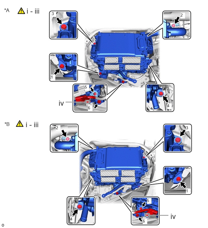
| *A | for LHD | *B | for RHD |
Temporarily install the No. 6 inverter bracket with the 2 bolts.
- NOTICE:
- ·
Since the inverter with converter assembly is very heavy, 2 people are needed to install the inverter with converter assembly. When installing the inverter with converter assembly, do not damage the parts around it.
·To prevent damage, do not hold the inverter with converter assembly by the connectors.
·To prevent damage due to static electricity, do not touch the terminals of the disconnected connectors.
Temporarily install the inverter with converter assembly with the 4 bolts.
Tighten the 6 bolts in the order shown in the illustration.
- Torque:
- 8.0 N*m (82 kgf*cm, 71 in.*lbf)
Attach the clamp.
G9A2C
6.INSTALL FC JUNCTION CABLE
|
|
|
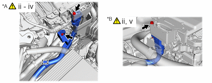
| *A | for LHD | *B | for RHD |
Remove the connector cover assembly.
Click hereEngine / Hybrid System>HYBRID / BATTERY CONTROL>INVERTER WITH CONVERTER>REMOVAL
Connect the FC junction cable.
- NOTICE:
- ·
Do not allow any foreign matter or water to enter the inverter with converter assembly.
·Do not touch the connector waterproofing rubber or terminals.
·Do not damage the connectors, connector housings or inverter with converter assembly during connection.
·Make sure that the connector is fully engaged.
for LHD:
Secure the FC junction cable to the inverter with converter assembly with the 2 bolts.
- Torque:
- 8.0 N*m (82 kgf*cm, 71 in.*lbf)
for LHD:
Engage the clamp.
Secure the FC junction cable to the inverter with converter assembly with the bolt.
- Torque:
- 8.0 N*m (82 kgf*cm, 71 in.*lbf)
Temporarily install the connector cover assembly.
Click hereEngine / Hybrid System>HYBRID / BATTERY CONTROL>INVERTER WITH CONVERTER>REMOVAL
82111C
7.INSTALL FRONT COMPARTMENT MAIN WIRE
|
|
|
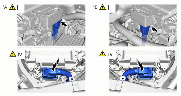
| *A | for LHD | *B | for RHD |
Remove the connector cover assembly.
Click hereEngine / Hybrid System>HYBRID / BATTERY CONTROL>INVERTER WITH CONVERTER>REMOVAL
Connect the front compartment main wire to the inverter with converter assembly.
- NOTICE:
- ·
Do not allow any foreign matter or water to enter the inverter with converter assembly.
·Do not touch the connector waterproofing rubber or terminals.
·Do not damage the connectors, connector housings or inverter with converter assembly during connection.
·Make sure that the connector is fully engaged.
Temporarily install the connector cover assembly.
Click hereEngine / Hybrid System>HYBRID / BATTERY CONTROL>INVERTER WITH CONVERTER>REMOVAL
Connect the front compartment main wire to the inverter with converter assembly and lock the connector with the lock lever as shown in the illustration.
G9205A
8.CONNECT INVERTER BUS-BAR PLATE SUB-ASSEMBLY
|
|
|
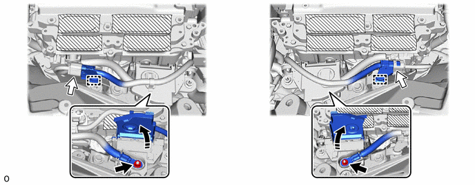
| *A | for LHD | *B | for RHD |
- Torque:
- 8.0 N*m (82 kgf*cm, 71 in.*lbf)
87209C
9.CONNECT WATER HOSE SUB-ASSEMBLY C (for RHD)
10.INSTALL WIRE HARNESS CLAMP BRACKET
- Torque:
- 8.0 N*m (82 kgf*cm, 71 in.*lbf)
G91C3
11.CONNECT NO. 3 FC INVERTER COOLING HOSE
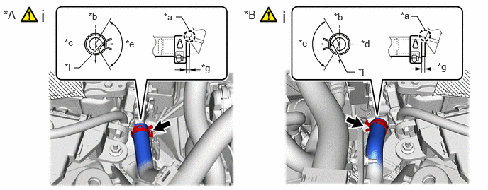
| *A | for LHD | *B | for RHD |
| *a | Insert | *b | Upper |
| *c | RH Side | *d | LH Side |
| *e | 120° | *f | Mark (White) |
| *g | 2.0 to 7.0 mm (0.079 to 0.275 in.) | - | - |
Connect the No. 3 FC inverter cooling hose to the inverter with converter assembly and slide the hose clip to secure it.
- NOTICE:
-
Do not remove the pieces of cloth or plastic bags from the pipe and disconnected hose until installation.
- HINT:
-
Make sure that the hose clip is positioned as shown in the illustration.
G90A1
12.CONNECT NO. 1 FC INVERTER COOLING HOSE SUB-ASSEMBLY
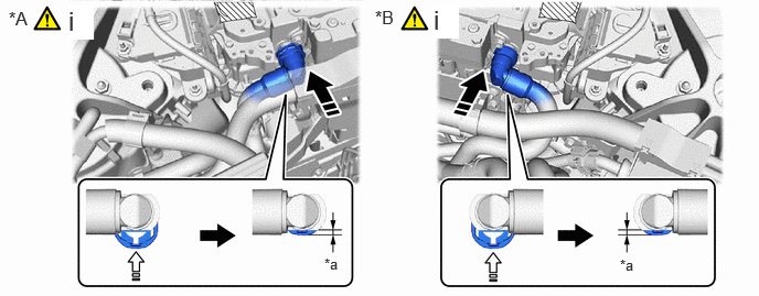
| *A | for LHD | *B | for RHD |
| *a | 2.5 mm (0.098 in.) or less | - | - |
Connect the No. 1 FC inverter cooling hose sub-assembly to the inverter with converter assembly and lock the hose with the retainer as shown in the illustration.
- NOTICE:
- ·
Push in the retainer until a click sound is heard.
·Pull on the pipe to confirm that the pipe is securely connected.
·If there is foreign matter on the union or the O-ring, clean it with water and finger scouring.
·To prevent foreign matter from entering the cooling system, do not remove the pieces of cloth or plastic bags from the pipe and disconnected hose until installation.
53705F
13.INSTALL FENDER APRON BRACE SUB-ASSEMBLY RH (for LHD)
- Torque:
- 49 N*m (500 kgf*cm, 36 ft.*lbf)
53706A
14.INSTALL FENDER APRON BRACE SUB-ASSEMBLY LH (for RHD)
- Torque:
- 49 N*m (500 kgf*cm, 36 ft.*lbf)
G9200A
15.CONNECT FC CONVERTER POWER OUTLET CABLE (INVERTER WITH CONVERTER ASSEMBLY)
|
|
|
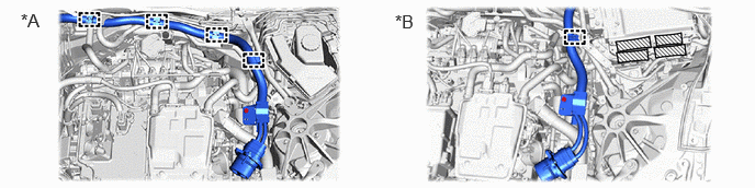
| *A | for LHD | *B | for RHD |
If the FC converter power outlet front holder and FC converter power outlet front gasket are removed, install them using the following procedure.
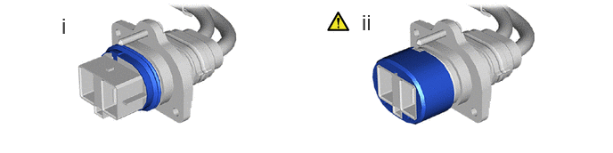
Install the FC converter power outlet front gasket to the housing.
- HINT:
-
Install by aligning the protrusion of the FC converter power outlet front gasket with the housing groove.
Install the FC converter power outlet front holder to the housing.
- NOTICE:
-
Push in the FC converter power outlet front holder until a "click" sound is heard. After pushing it in, check that it is not removed.
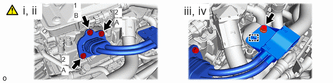
Connect the FC converter power outlet cable (inverter with converter assembly) to the FC stack assembly.
Tighten the 2 bolts (A) and bolt (B) in the order shown in the illustration.
- Torque:
- 8.0 N*m (82 kgf*cm, 71 in.*lbf)
- NOTICE:
-
Installing the bolts in an incorrect order may damage the FC stack assembly and FC converter power outlet cable (inverter with converter assembly).
Engage the clamp.
Install the bolt.
- Torque:
- 8.0 N*m (82 kgf*cm, 71 in.*lbf)
G1240C
16.INSTALL INVERTER MOTOR CABLE BRACKET ASSEMBLY
- Torque:
- 8.0 N*m (82 kgf*cm, 71 in.*lbf)
821H3B
17.CONNECT NO. 2 BATTERY PACK WIRE
|
|
|
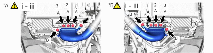
| *A | for LHD | *B | for RHD |
Temporarily install the No. 2 battery pack wire to the inverter with converter assembly with the 5 bolts.
- NOTICE:
- ·
Do not allow any foreign matter or water to enter the inverter with converter assembly.
·Do not touch the connector waterproofing rubber or terminals.
·Do not damage the terminals, connector housings or inverter with converter assembly when connecting them.
Using an insulated tool, tighten the 3 bolts (A) in the order shown in the illustration.
- Torque:
- 8.0 N*m (82 kgf*cm, 71 in.*lbf)
Using an insulated tool, tighten the 2 bolts (B).
- Torque:
- 8.0 N*m (82 kgf*cm, 71 in.*lbf)
17A90
18.CONNECT FC AIR COMPRESSOR MOTOR CABLE ASSEMBLY
|
|
|
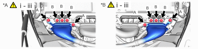
| *A | for LHD | *B | for RHD |
Temporarily install the FC air compressor motor cable assembly to the inverter with converter assembly with the 5 bolts.
- NOTICE:
- ·
Do not allow any foreign matter or water to enter the inverter with converter assembly.
·Do not touch the connector waterproofing rubber or terminals.
·Do not damage the terminals, connector housings or inverter with converter assembly when connecting them.
Using an insulated tool, tighten the 2 bolts (A).
- Torque:
- 8.0 N*m (82 kgf*cm, 71 in.*lbf)
Using an insulated tool, tighten the 3 bolts (B).
- Torque:
- 8.0 N*m (82 kgf*cm, 71 in.*lbf)
G9223B
19.INSTALL INVERTER TERMINAL COVER
|
|
|
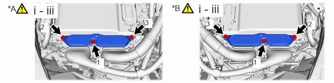
| *A | for LHD | *B | for RHD |
Temporarily install the inverter terminal cover to the inverter with converter assembly.
- NOTICE:
- ·
Do not touch the inverter terminal cover waterproofing rubber.
·Do not allow any foreign matter or water to enter the inverter with converter assembly.
·Make sure that the interlock is fully engaged.
Press the inverter terminal cover by hand until it is firmly attached to the inverter with converter assembly.
Tighten the 3 bolts to the inverter terminal cover.
- Torque:
- 8.0 N*m (82 kgf*cm, 71 in.*lbf)
- NOTICE:
-
Tighten the 3 bolts in the sequence shown in the illustration.
20.INSTALL CONNECTOR COVER ASSEMBLY
|
|
|
- Torque:
- 8.0 N*m (82 kgf*cm, 71 in.*lbf)
G3834
21.INSTALL SERVICE PLUG GRIP
22.ADD COOLANT (for Inverter)
23.INSPECT FOR COOLANT LEAK (for Inverter)
55708
24.INSTALL COWL TOP VENTILATOR LOUVER SUB-ASSEMBLY
1A906
25.INSTALL FC STACK COVER SUB-ASSEMBLY
53295
26.INSTALL LOWER RADIATOR AIR DEFLECTOR
53291B
27.INSTALL RADIATOR COVER PLATE
53292A
28.INSTALL UPPER RADIATOR SUPPORT SEAL