BRAKE CONTROL / DYNAMIC CONTROL SYSTEMS ELECTRONICALLY CONTROLLED BRAKE SYSTEM C13807F Stop Lamp Relay Actuator Stuck Off
DESCRIPTION
Refer to DTC C13807E.
Click hereBrake>BRAKE CONTROL / DYNAMIC CONTROL SYSTEMS>ELECTRONICALLY CONTROLLED BRAKE SYSTEM>C13807E
| DTC No. | Detection Item | DTC Detection Condition | Trouble Area | DTC Output from | Priority | Note |
|---|---|---|---|---|---|---|
| C13807F | Stop Lamp Relay Actuator Stuck Off | Either of the following is detected:
·
When the IG1 terminal voltage exceeds 10 V and the +BS terminal voltage is from 9.5 to 17.4 V, stop light drive output (STPO) is ON, STP is OFF and STP2 is OFF continuously for 2 seconds or more. ·
When the IG1 terminal voltage exceeds 10 V and the +BS terminal voltage is from 9.5 to 17.4 V, STP2 is OFF and STP is ON continuously for 5 seconds or more. |
·
Wire harness and connector ·
Stop light switch assembly ·
No. 2 skid control ECU (brake actuator assembly) ·
No. 2 semiconductor power integration ECU ·
STP circuit ·
STP2 circuit |
Brake/EPB | B | Output ECU: No. 2 skid control ECU (brake actuator assembly) |
| Vehicle Condition | |||
|---|---|---|---|
| Pattern 1 | Pattern 2 | ||
| Diagnosis Condition | When the IG1 terminal voltage exceeds 10 V and the +BS terminal voltage is from 9.5 to 17.4 V | ○ | ○ |
| Malfunction Status | Stop light drive output (STPO) is ON, STP is OFF and STP2 is OFF continuously | ○ | - |
| STP2 is OFF and STP is ON continuously | - | ○ | |
| Detection Time | 2 seconds or more. | 5 seconds or more. | |
| Number of Trips | 1 trip | 1 trip | |
- HINT:
-
DTC will be output when conditions for either of the patterns in the table above are met.
WIRING DIAGRAM
Refer to DTC C13807E.
Click hereBrake>BRAKE CONTROL / DYNAMIC CONTROL SYSTEMS>ELECTRONICALLY CONTROLLED BRAKE SYSTEM>C13807E
CAUTION / NOTICE / HINT
- NOTICE:
- ·
Inspect the fuses for circuits related to this system before performing the following procedure.
·After replacing the No. 2 skid control ECU (brake actuator assembly), perform "Calibration".
Click hereBrake>BRAKE CONTROL / DYNAMIC CONTROL SYSTEMS>ELECTRONICALLY CONTROLLED BRAKE SYSTEM>UTILITY
- HINT:
-
When DTC P057112 and/or P057113 are output together with DTC C13807F, inspect and repair the trouble areas indicated by DTC P057112 and/or P057113 first.
-
for P057112: Click hereBrake>BRAKE CONTROL / DYNAMIC CONTROL SYSTEMS>ELECTRONICALLY CONTROLLED BRAKE SYSTEM>P057112
-
for P057113: Click hereBrake>BRAKE CONTROL / DYNAMIC CONTROL SYSTEMS>ELECTRONICALLY CONTROLLED BRAKE SYSTEM>P057113
PROCEDURE
Perform the stop light control relay (No. 2 semiconductor power integration ECU) Active Test, and confirm that the stop lights illuminate and turn off and the value of "Stop Light SW", "Stop Light Relay" and "STPO" changes.
- Chassis > Brake/EPB > Active Test
-
Tester Display Measurement Item Control Range Restrict Condition Diagnostic Note Stop Lamp Relay Stop light control relay (No. 2 semiconductor power integration ECU) OFF / ON Vehicle condition: Vehicle stopped
- HINT:
-
To protect this Actuator and Solenoid, this test will only last 5 seconds.
With the brake pedal released, check that the stop lights illuminate and the value of Stop Light Relay on the GTS changes to ON when Stop Lamp Relay is ON
- Chassis > Brake/EPB > Data List
-
Tester Display Measurement Item Range Normal Condition Diagnostic Note Stop Light SW Stop light switch assembly status
(STP or STP2 terminal input)OFF / ON OFF: Brake pedal released
ON: Brake pedal depressed- HINT:
- ·
Stop light control relay off: STP terminal status displayed.
·Stop light control relay on: STP2 terminal status displayed.
- Chassis > Brake/EPB > Active Test
-
Active Test Display Stop Lamp Relay -
Data List Display Stop Light SW - 50004 435 27 59
- Result:
Result Proceed to The value of Stop Light SW is OFF A The value of Stop Light SW is ON B
A
B
for LHD: Click hereBrake>BRAKE CONTROL / DYNAMIC CONTROL SYSTEMS>BRAKE ACTUATOR (for LHD)>REMOVAL
for RHD: Click hereBrake>BRAKE CONTROL / DYNAMIC CONTROL SYSTEMS>BRAKE ACTUATOR (for RHD)>REMOVAL
Perform the stop light control relay (No. 2 semiconductor power integration ECU) Active Test, and confirm that the stop lights illuminate.
- Chassis > Brake/EPB > Active Test
-
Tester Display Measurement Item Control Range Restrict Condition Diagnostic Note Stop Lamp Relay Stop light control relay (No. 2 semiconductor power integration ECU) OFF / ON Vehicle condition: Vehicle stopped
- HINT:
-
To protect this Actuator and Solenoid, this test will only last 5 seconds.
With the brake pedal released, check that the stop lights illuminate and the value of Stop Light Relay on the GTS changes to ON when Stop Lamp Relay is ON
- Chassis > Brake/EPB > Active Test
-
Tester Display Stop Lamp Relay - 50004 435 27
- Result:
Result Proceed to The stop lights are not illuminated. A The stop lights are illuminated. B
A
B
Pre-procedure1
Turn the ignition switch off.
Procedure1
Make sure that there is no looseness at the locking part and the connecting part of the connectors.
- OK:
The connector is securely connected.
Pre-procedure2
Disconnect the A6 No. 2 skid control ECU (brake actuator assembly) connector.
Procedure2
Check both the connector case and the terminals for deformation and corrosion.
- OK:
No deformation or corrosion.
Procedure3
Measure the voltage according to the value(s) in the table below.
- Standard Voltage:
Tester Connection Condition Specified Condition Click Location & Routing(A6)Location & Routingewd_type=routing;type=c;code=A6
A6-32 (STPO) - Body ground Always 11 to 14 V
- Result:
Proceed to OK NG
Post-procedure1
None
OK
NG
Make sure that there is no looseness at the locking part and the connecting part of the connectors.
- OK:
The connector is securely connected.
Check both the connector case and the terminals for deformation and corrosion.
- OK:
No deformation or corrosion.
Measure the voltage according to the value(s) in the table below.
- Standard Voltage:
Tester Connection Condition Specified Condition Click Location & Routing(A6)Location & Routingewd_type=routing;type=c;code=A6
A6-37 (STP2) - Body ground Stop light switch assembly on (Brake pedal depressed) 11 to 14 V
- Result:
Proceed to OK NG
OK
for LHD: Click hereBrake>BRAKE CONTROL / DYNAMIC CONTROL SYSTEMS>BRAKE ACTUATOR (for LHD)>REMOVAL
for RHD: Click hereBrake>BRAKE CONTROL / DYNAMIC CONTROL SYSTEMS>BRAKE ACTUATOR (for RHD)>REMOVAL
NG
Check that there is no short to ground in the STP2 circuit (wire harnesses, connectors, stop lights and ECUs)
- OK:
There is no short to ground.
- Result:
Proceed to OK NG
OK
NG
Procedure1
Make sure that there is no looseness at the locking part and the connecting part of the connectors.
- OK:
The connector is securely connected.
Pre-procedure1
Disconnect the G102 No. 2 semiconductor power integration ECU connector.
Procedure2
Check both the connector case and the terminals for deformation and corrosion.
- OK:
No deformation or corrosion.
Procedure3
Measure the resistance according to the value(s) in the table below.
- Standard Resistance:
Tester Connection Condition Specified Condition Click Location & Routing(G102,A6)Location & Routingewd_type=routing;type=c,c;code=G102,A6
Click Connector(G102)Body>Floor Wire / No. 3 Floor Wire>No. 2 Semiconductor Power Integration ECUewd_type=component;type=c;code=G102;pinno=1
G102-1 (OUT) - A6-37 (STP2) Always Below 1 Ω
- Result:
Proceed to OK NG
Post-procedure1
None
OK
NG
Make sure that there is no looseness at the locking part and the connecting part of the connectors.
- OK:
The connector is securely connected.
Check both the connector case and the terminals for deformation and corrosion.
- OK:
No deformation or corrosion.
Measure the resistance according to the value(s) in the table below.
- Standard Resistance:
Tester Connection Condition Specified Condition Click Location & Routing(G102,A6)Location & Routingewd_type=routing;type=c,c;code=G102,A6
Click Connector(G102)Body>Floor Wire / No. 3 Floor Wire>No. 2 Semiconductor Power Integration ECUewd_type=component;type=c;code=G102;pinno=10
G102-10 (STP) - A6-11 (STP) Always Below 1 Ω
- Result:
Proceed to OK NG
OK
NG
Make sure that there is no looseness at the locking part and the connecting part of the connectors.
- OK:
The connector is securely connected.
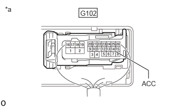
| *a | Component with harness connected
(No. 2 Semiconductor Power Integration ECU) |
Measure the voltage according to the value(s) in the table below.
- Standard Voltage:
Tester Connection Condition Specified Condition Click Location & Routing(G102)Location & Routingewd_type=routing;type=c;code=G102
Click Connector(G102)Body>Floor Wire / No. 3 Floor Wire>No. 2 Semiconductor Power Integration ECUewd_type=component;type=c;code=G102;pinno=14
G102-14 (ACC) - Body ground Always 11 to 14 V
- Result:
Proceed to OK NG
OK
NG
Pre-procedure1
Turn the ignition switch off.
Procedure1
Make sure that there is no looseness at the locking part and the connecting part of the connectors.
- OK:
The connector is securely connected.
Pre-procedure2
Disconnect the A6 No. 2 skid control ECU (brake actuator assembly) connector.
Procedure2
Check both the connector case and the terminals for deformation and corrosion.
- OK:
No deformation or corrosion.
Procedure3
Measure the voltage according to the value(s) in the table below.
- Standard Voltage:
Tester Connection Condition Specified Condition Click Location & Routing(A6)Location & Routingewd_type=routing;type=c;code=A6
A6-37 (STP2) - Body ground Stop light switch assembly on (Brake pedal depressed) 11 to 14 V
- Result:
Proceed to OK NG
Post-procedure1
None
OK
for LHD: Click hereBrake>BRAKE CONTROL / DYNAMIC CONTROL SYSTEMS>BRAKE ACTUATOR (for LHD)>REMOVAL
for RHD: Click hereBrake>BRAKE CONTROL / DYNAMIC CONTROL SYSTEMS>BRAKE ACTUATOR (for RHD)>REMOVAL
NG