BRAKE SYSTEM (OTHER) BRAKE BOOSTER(for LHD) INSTALLATION
CAUTION / NOTICE / HINT
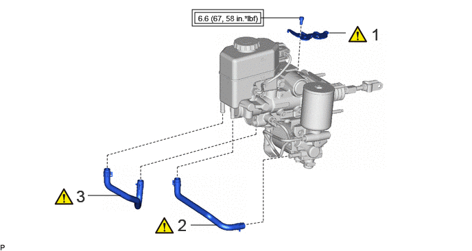
| Procedure | Part Name Code | 
|

|

|
|
|---|---|---|---|---|---|
| 1 | NO. 1 WIRE CLAMP BRACKET | - | ( ) |
- | - |
| 2 | NO. 2 RESERVOIR HOSE | - | ()
|
- | - |
| 3 | NO. 1 RESERVOIR HOSE | - | ()
|
- | - |

|
Tightening torque for "Major areas involving basic vehicle performance such as moving/turning/stopping": N*m (kgf*cm, ft.*lbf) | - | - |
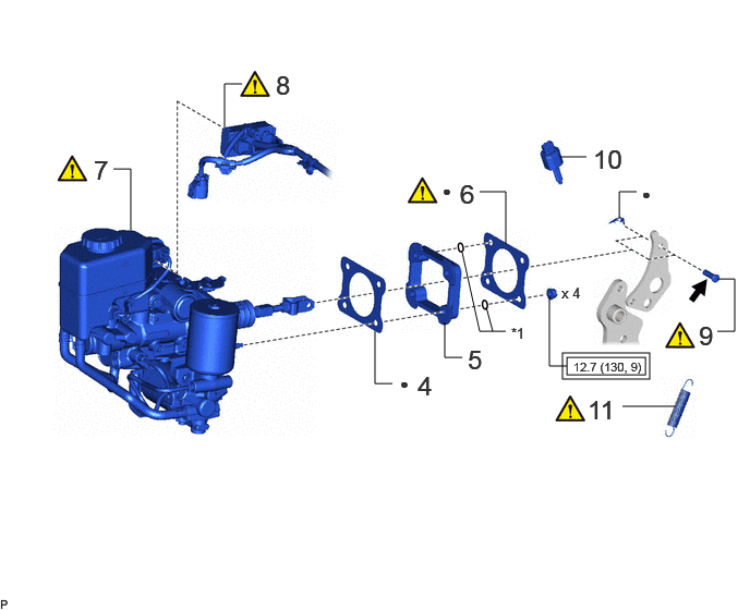
| Procedure | Part Name Code |
|
|
|
|
|---|---|---|---|---|---|
| 4 | BRAKE MASTER CYLINDER GASKET | 44785D | - | - | - |
| 5 | BRAKE BOOSTER BRACKET | - | - | - | - |
| 6 | BRAKE MASTER CYLINDER GASKET | 44785D | ()
|
- | - |
| 7 | BRAKE BOOSTER WITH MASTER CYLINDER ASSEMBLY | 47210L | ()
|
- | - |
| 8 | FRONT COMPARTMENT MAIN WIRE | 82111C | ()
|
- | - |
| 9 | PUSH ROD PIN | 47264A | ()
|
- | - |
| 10 | STOP LIGHT SWITCH ASSEMBLY | 84340 | - | - | - |
| 11 | BRAKE PEDAL RETURN SPRING | 47101A | ()
|
- | - |
| *1 | BOOSTER BRACKET STOPPER RING
(The booster bracket stopper ring is used as a jig during assembly at the factory.When installing the brake booster assembly, it is not necessary to install a booster bracket stopper ring.) |
- | - |
|
|
Tightening torque for "Major areas involving basic vehicle performance such as moving/turning/stopping": N*m (kgf*cm, ft.*lbf) | ● | Non-reusable part |

|
Lithium soap base glycol grease | - | - |
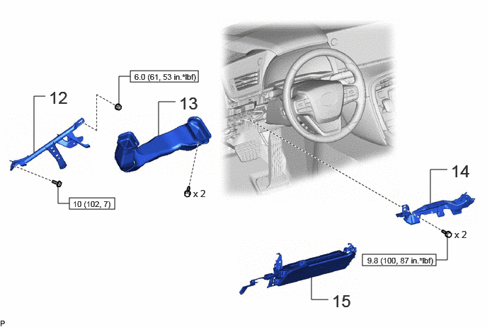
| Procedure | Part Name Code |
|
|
|
|
|---|---|---|---|---|---|
| 12 | NO. 3 INSTRUMENT PANEL TO COWL BRACE SUB-ASSEMBLY | 55308B | - | - | - |
| 13 | NO. 2 HEATER TO REGISTER DUCT | 55844 | - | - | - |
| 14 | AIR DUCT SUB-ASSEMBLY | - | - | - | - |
| 15 | LOWER NO. 1 INSTRUMENT PANEL AIRBAG ASSEMBLY | 73900 | - | - | - |

|
N*m (kgf*cm, ft.*lbf): Specified torque | - | - |
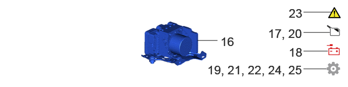
| Procedure | Part Name Code |
|
|
|
|
|---|---|---|---|---|---|
| 16 | BRAKE ACTUATOR WITH BRACKET | - | - | - | - |
| 17 | FILL RESERVOIR WITH BRAKE FLUID | - | - | - | - |
| 18 | CONNECT CABLE TO NEGATIVE AUXILIARY BATTERY TERMINAL | - | - | - | - |
| 19 | UPDATE ECU SECURITY KEY | - | - | - | ()
|
| 20 | BLEED BRAKE SYSTEM | - | - | ()
|
- |
| 21 | INSPECT AND ADJUST BRAKE PEDAL | - | - | - | ()
|
| 22 | PERFORM CALIBRATION | - | - | - | ()
|
| 23 | CHECK AND CLEAR DTC | - | - | - | - |
| 24 | INSPECT SRS WARNING LIGHT | - | - | - | ()
|
| 25 | INITIALIZATION AFTER RECONNECTING AUXILIARY BATTERY TERMINAL | - | - | - | ()
|
CAUTION / NOTICE / HINT
- NOTICE:
-
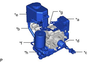 0.688,0.5 0.938,0.5 false 0.75,1 1,1 false 0.833,1.5 1.083,1.5 false 1.031,1.833 1.281,1.833 false 2.667,1.833 2.917,1.833 false 2.292,1.5 2.458,1.417 2.458,1.417 2.625,1.417 false 2.375,0.667 2.625,0.667 false 1.719,0.99 1.885,0.406 1.885,0.406 2.052,0.406 true 2.677,0.604 3.01,0.854 0.333,0.25 10 false *a 0.573,0.938 0.906,1.188 0.333,0.25 10 false *b 2.969,1.771 3.219,2.021 0.25,0.25 10 false *c 2.677,1.354 2.927,1.604 0.25,0.25 10 false *d 0.51,0.438 0.844,0.604 0.333,0.167 10 false *e 0.688,1.438 0.938,1.688 0.25,0.25 10 false *f 2.094,0.344 2.344,0.594 0.25,0.25 10 false *g 0.865,1.771 1.198,2.021 0.333,0.25 10 false *h
*a No. 1 Skid Control ECU *b No. 1 Reservoir Hose and No. 2 Reservoir Hose *c Master Cylinder Push Rod Clevis *d Boot *e Brake Master Cylinder Reservoir *f No. 1 Brake Actuator Tube *g No. 1 Wire Clamp Bracket *h Brake Booster with Accumulator Pump Assembly
-
Do not carry the brake booster with master cylinder assembly by the parts shown in the illustration.
PROCEDURE

 1.INSTALL NO. 1 WIRE CLAMP BRACKET
|
|
|
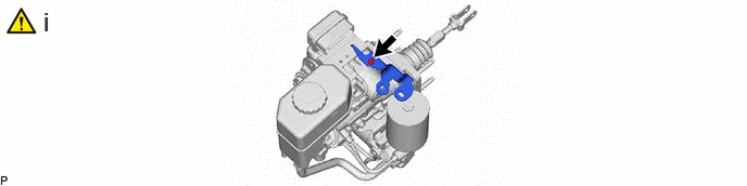
Using a 5 mm long hexagon socket wrench, install the No. 1 wire clamp bracket with the bolt.
- Torque:
- 6.6 N*m (67 kgf*cm, 58 in.*lbf)
2.INSTALL NO. 2 RESERVOIR HOSE
|
|
|
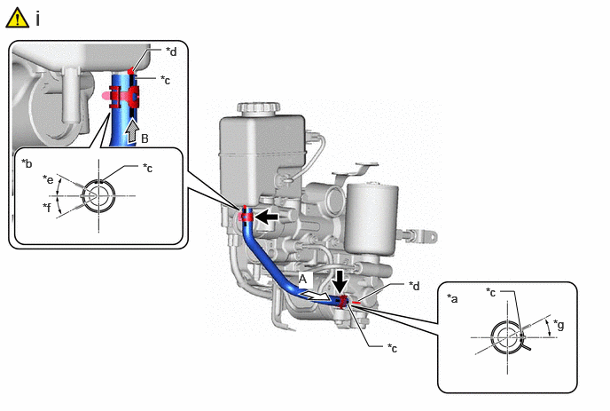
| *a | View A | *b | View B |
| *c | Paint Mark | *d | Rib |
| *e | within 40° | *f | within 70° |
| *g | within 45° | - | - |
Install the No. 2 reservoir hose, and slide the 2 clips to secure it.
- NOTICE:
- ·
Make sure that the paint mark is facing the front of the vehicle (Upper Side).
·Make sure that the paint mark is outside of the vehicle (Lower Side).
·Install the clip within the range shown in the illustration.
3.INSTALL NO. 1 RESERVOIR HOSE
|
|
|
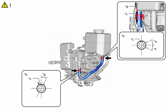
| *a | View A | *b | View B |
| *c | Paint Mark | *d | Rib |
| *e | within 40° | *f | within 70° |
| *g | within 45° | - | - |
Install the No. 1 reservoir hose, and slide the 2 clips to secure it.
- NOTICE:
- ·
Make sure that the paint mark is facing the front of the vehicle.
·Install the clip within the range shown in the illustration.
44785D
4.INSTALL BRAKE MASTER CYLINDER GASKET
5.INSTALL BRAKE BOOSTER BRACKET
44785D
6.INSTALL BRAKE MASTER CYLINDER GASKET
|
|
|
47210L
7.INSTALL BRAKE BOOSTER WITH MASTER CYLINDER ASSEMBLY
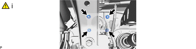
Install the brake booster with master cylinder assembly with the 4 nuts.
- Torque:
- 12.7 N*m (130 kgf*cm, 9 ft.*lbf)
- NOTICE:
- ·
Do not apply excessive force to the brake lines.
·Be careful not to allow brake fluid to enter the connector.
·If installing a new brake booster with master cylinder assembly, do not remove the hole plugs before connecting the brake lines because the brake booster with master cylinder assembly is filled with brake fluid.
·
0.688,0.5 0.938,0.5 false 0.75,1 1,1 false 0.833,1.5 1.083,1.5 false 1.031,1.833 1.281,1.833 false 2.667,1.833 2.917,1.833 false 2.292,1.5 2.458,1.417 2.458,1.417 2.625,1.417 false 2.375,0.667 2.625,0.667 false 1.719,0.99 1.885,0.406 1.885,0.406 2.052,0.406 true 2.677,0.604 3.01,0.854 0.333,0.25 10 false *a 0.573,0.938 0.906,1.188 0.333,0.25 10 false *b 2.969,1.771 3.219,2.021 0.25,0.25 10 false *c 2.677,1.354 2.927,1.604 0.25,0.25 10 false *d 0.51,0.438 0.844,0.604 0.333,0.167 10 false *e 0.688,1.438 0.938,1.688 0.25,0.25 10 false *f 2.094,0.344 2.344,0.594 0.25,0.25 10 false *g 0.865,1.771 1.198,2.021 0.333,0.25 10 false *h*a No. 1 Skid Control ECU *b No. 1 Reservoir Hose and No. 2 Reservoir Hose *c Master Cylinder Push Rod Clevis *d Boot *e Brake Master Cylinder Reservoir *f No. 1 Brake Actuator Tube *g No. 1 Wire Clamp Bracket *h Brake Booster with Accumulator Pump Assembly
Do not carry the brake booster with master cylinder assembly by the parts shown in the illustration.
82111C
8.CONNECT FRONT COMPARTMENT MAIN WIRE
|
|
|
47264A
9.INSTALL PUSH ROD PIN
|
|
Click here()
|
84340
10.INSTALL STOP LIGHT SWITCH ASSEMBLY
47101A
11.INSTALL BRAKE PEDAL RETURN SPRING
|
|
Click here()
|
55308B
12.INSTALL NO. 3 INSTRUMENT PANEL TO COWL BRACE SUB-ASSEMBLY
55844
13.INSTALL NO. 2 HEATER TO REGISTER DUCT
14.INSTALL AIR DUCT SUB-ASSEMBLY
73900
15.INSTALL LOWER NO. 1 INSTRUMENT PANEL AIRBAG ASSEMBLY
16.INSTALL BRAKE ACTUATOR WITH BRACKET
17.FILL RESERVOIR WITH BRAKE FLUID
18.CONNECT CABLE TO NEGATIVE AUXILIARY BATTERY TERMINAL
19. UPDATE ECU SECURITY KEY
20.BLEED BRAKE SYSTEM
21.INSPECT AND ADJUST BRAKE PEDAL
22.PERFORM CALIBRATION
23. CHECK AND CLEAR DTC
24.INSPECT SRS WARNING LIGHT
25. INITIALIZATION AFTER RECONNECTING AUXILIARY BATTERY TERMINAL
Click hereGeneral>SETUP>WHEN DISCONNECTING OR RECONNECTING BATTERY TERMINAL>WORK PROCEDURE
- HINT:
-
When disconnecting and reconnecting the battery, there is an automatic learning function that completes learning when the respective system is used.
-
Click hereGeneral>SETUP>WHEN DISCONNECTING OR RECONNECTING BATTERY TERMINAL>AUTOMATIC LEARNING CHART