| YES |  |
| GO TO RELEVANT DTC CHART |
DTC P0A94-547 DC / DC Converter Performance |
DTC P0A94-548 DC / DC Converter Performance |
DTC P0A94-549 DC / DC Converter Performance |
| DTC No. | INF Code | DTC Detection Condition | Trouble Area |
| P0A94 | 547 | Boost converter over-voltage (OVL) signal detection (over-voltage by HV control ECU malfunction) |
|
| P0A94 | 548 | Boost converter over-voltage (OVL) signal detection (over-voltage by inverter assembly malfunction) |
|
| P0A94 | 549 | Boost converter over-voltage (OVL) signal detection (over-voltage by HV transaxle assembly malfunction) |
|
| Related DTCs | P0A94 (INF 547 / 548 / 549): OVL detection over-voltage |
| Required sensor / components | Boost converter |
| Frequency of operation | Continuous |
| Duration | TOYOTA's intellectual property |
| MIL operation | Immediately |
| Sequence of operation | None |
| The monitor will run whenever the following DTCs are not present | TOYOTA's intellectual property |
| Other conditions belong to TOYOTA's intellectual property | - |
| Boost converter | Over-voltage |
| Boost converter | DTC P0A94 (INF 547 / 548 / 549) is not detected |
| 1.CONFIRM INFORMATION (EXCLUSIVE INFO 3) |
Connect the Techstream to the DLC3.
Turn the power switch ON (IG).
Enter the following menus: Powertrain / Hybrid Control / Trouble Codes.
Select DTC P0A94 to display its freeze frame data.
Select the item that has INF code 547, 548, or 549 from among "Detail Code 1 to 5, Detail Information 1 to 5" and press ENTER.
Read "Exclusive Information 3".
|
| ||||
| NO | |
 |
| 2.CHECK CONNECTION CONDITION OF HYBRID VEHICLE CONTROL ECU CONNECTOR (LOOSENESS AND POOR CONTACT) |
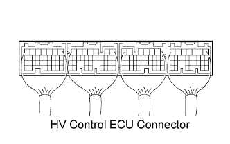 |
Check the connection condition of all the connectors at the HV control ECU.
|
| ||||
| OK | |
|
| 3.CHECK CONNECTION CONDITION OF INVERTER CONNECTOR (LOOSENESS AND POOR CONTACT) |
Turn the power switch OFF.
Remove the service plug grip .
Remove the inverter cover .
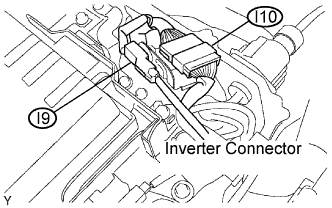 |
Check the connection condition of the I9 and I10 inverter connectors.
Reinstall the inverter cover .
Reinstall the service plug grip .
|
| ||||
| OK | |
|
| 4.CONFIRM INFORMATION (EXCLUSIVE INFO 4) |
Connect the Techstream to the DLC3.
Turn the power switch ON (IG).
Enter the following menus: Powertrain / Hybrid Control / Trouble Codes.
Select DTC P0A94 to display its freeze frame data.
Select the item that has INF code 547, 548, or 549 from among "Detail Code 1 to 5, Detail Information 1 to 5" and press ENTER.
Read "Exclusive Information 4".
| Displayed in Exclusive Information 4 | Proceed to |
| -127 to -120, -95 to -88, -63 to -56, -31 to -24, 1 to 8, 33 to 40, 65 to 72, 97 to 104 | A |
| -119 to -112, -87 to -80, -55 to -48, -23 to -16, 9 to 16, 41 to 48, 73 to 80, 105 to 112 | B |
| -111 to -104, -79 to -72, -47 to -40, -15 to -8, 17 to 24, 49 to 56, 81 to 88, 113 to 120 | C |
| -103 to -96, -71 to -64, -39 to -32, -7 to 0, 25 to 32, 57 to 64, 89 to 96, 121 to 127 | D |
|
| ||||
|
| ||||
|
| ||||
| A | |
|
| 5.READ OUTPUT DTC (HV ECU) |
Connect the Techstream to the DLC3.
Turn the power switch ON (IG).
Enter the following menus: Powertrain / Hybrid Control / Trouble Codes.
Check if DTCs are output.
| DTC No. | INF Code | Detection Item | See Page |
| P0A78 | 266 | Drive Motor "A" Inverter Performance |
Click here
|
| P0A94 | 558 or 560 | DC / DC Converter Performance |
Click here
|
| P0A94 | 588 | DC / DC Converter Performance |
Click here
|
| P0A94 | 589 | DC / DC Converter Performance |
Click here
|
| P0ADB | 227 | Hybrid Battery Positive Contactor Control Circuit Low |
Click here
|
| P0ADF | 229 | Hybrid Battery Negative Contactor Control Circuit Low |
Click here
|
| P3000 | 125 | HV Battery Malfunction |
Click here
|
| P3004 | 131 | Power Cable Malfunction |
Click here
|
|
| ||||
| NO | |
|
| 6.INSPECT HYBRID VEHICLE MOTOR ASSEMBLY |
Turn the power switch OFF.
Remove the service plug grip .
Remove the inverter cover .
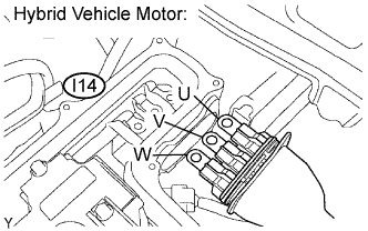 |
Disconnect the three-phase alternating current cable for the hybrid vehicle motor from the inverter.
Using a milliohm meter, measure the resistance between the three-phase alternating current cable terminals of the hybrid vehicle motor.
| Tester Connection | Specified Condition* |
| U (I14-1) - V (I14-2) | Below 135 mΩ at 68°F (20°C) |
| V (I14-2) - W (I14-3) | Below 135 mΩ at 68°F (20°C) |
| W (I14-3) - U (I14-1) | Below 135 mΩ at 68°F (20°C) |
Calculate the difference between the maximum and minimum resistance between terminals U - V, V - W, and W - U.
Using a megohmmeter, measure the insulation resistance between the three-phase alternating current cable terminals of the hybrid vehicle motor and the body ground.
| Tester Connection | Specified Condition |
| U (I14-1) - Body ground | 10 MΩ or higher |
| V (I14-2) - Body ground | 10 MΩ or higher |
| W (I14-3) - Body ground | 10 MΩ or higher |
Reconnect the three-phase alternating current cable for the hybrid vehicle motor.
|
| ||||
| OK | |
|
| 7.INSPECT HYBRID VEHICLE GENERATOR ASSEMBLY |
Check that the service plug grip and inverter cover have been removed.
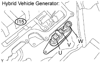 |
Disconnect the three-phase alternating current cable for the hybrid vehicle generator from the inverter.
Using a milliohm meter, measure the resistance between the three-phase alternating current cable terminals of the hybrid vehicle generator.
| Tester Connection | Specified Condition* |
| U (I15-1) - V (I15-2) | Below 109 mΩ at 68°F (20°C) |
| V (I15-2) - W (I15-3) | Below 109 mΩ at 68°F (20°C) |
| W (I15-3) - U (I15-1) | Below 109 mΩ at 68°F (20°C) |
Calculate the difference between the maximum and minimum resistance between terminals U - V, V - W, and W - U.
Using a megohmmeter, measure the insulation resistance between the three-phase alternating current cable terminals of the hybrid vehicle generator and the body ground.
| Tester Connection | Specified Condition |
| U (I15-1) - Body ground | 10 MΩ or higher |
| V (I15-2) - Body ground | 10 MΩ or higher |
| W (I15-3) - Body ground | 10 MΩ or higher |
Reconnect the three-phase alternating current cable for the hybrid vehicle generator.
|
| ||||
| OK | |
|
| 8.PERFORM ACTIVE TEST BY THE TECHSTREAM (FORCIBLE STOP OF INVERTER DRIVE) |
Check that the service plug grip and inverter cover have been removed.
Connect the Techstream to the DLC3.
Turn the power switch ON (IG).
Enter the following menus: Powertrain / Hybrid Control / Active Test.
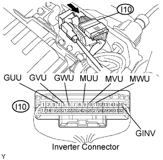 |
Measure the voltage between the terminals of the inverter connector while effecting "Forcible Stop of Inverter Drive".
| Tester Connection | Specified Condition |
| MUU (I10-9) - GINV (I10-16) | 12 to 16 V |
| MVU (I10-10) - GINV (I10-16) | 12 to 16 V |
| MWU (I10-11) - GINV (I10-16) | 12 to 16 V |
| GUU (I10-4) - GINV (I10-16) | 12 to 16 V |
| GVU (I10-5) - GINV (I10-16) | 12 to 16 V |
| GWU (I10-6) - GINV (I10-16) | 12 to 16 V |
Turn the power switch OFF.
|
| ||||
| NG | |
|
| 9.PERFORM ACTIVE TEST BY THE TECHSTREAM (FORCIBLE STOP OF INVERTER DRIVE) |
Check that the service plug grip and inverter cover have been removed.
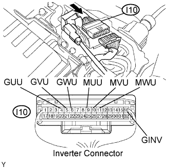 |
Disconnect the I10 inverter connector.
Connect the Techstream to the DLC3.
Turn the power switch ON (IG).
Enter the following menus: Powertrain / Hybrid Control / Active Test.
Measure the voltage between the terminals of the inverter connector while effecting "Forcible Stop of Inverter Drive".
| Tester Connection | Specified Condition |
| MUU (I10-9) - GINV (I10-16) | 14 to 16 V |
| MVU (I10-10) - GINV (I10-16) | 14 to 16 V |
| MWU (I10-11) - GINV (I10-16) | 14 to 16 V |
| GUU (I10-4) - GINV (I10-16) | 14 to 16 V |
| GVU (I10-5) - GINV (I10-16) | 14 to 16 V |
| GWU (I10-6) - GINV (I10-16) | 14 to 16 V |
Turn the power switch OFF.
Reconnect the inverter connector.
Reinstall the inverter cover .
Reinstall the service plug grip .
|
| ||||
| OK | ||
 | ||
| ||