BRAKE ACTUATOR > REPLACEMENT |
| 1. REPLACE BRAKE ACTUATOR ASSEMBLY |
Remove the windshield wiper motor and link (Click here).
Perform the accumulator pressure "ZERO DOWN" operation.
Move the shift lever to the P position. Apply the parking brake and connect the Techstream to the DLC3.
Turn the power switch ON (IG).
Turn on the Techstream. Enter the following menus: Chassis / ABS/VSC/ TRC / Utility / Electronically Controlled Brake system Utility / Zero Down.
Turn the power switch OFF.
Set the brake control (ELECTRONICALLY CONTROLLED BRAKE SYSTEM) off.
![]() |
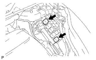
With the power switch OFF to prohibit brake control, remove the No. 1 and No. 2 motor relays.
Remove the outer front cowl top panel .
Remove the inverter with converter (Click here).
Drain brake fluid.
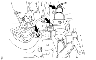
Separate the water pump with motor and bracket.
![]() |
Disconnect the connector.
Remove the 2 bolts and disconnect the water pump from the gusset.
![]() |
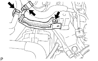
Remove the 2 clamps, bolt and heater hose bracket from the gusset.
Remove the brake actuator with bracket.
![]() |
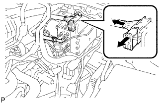
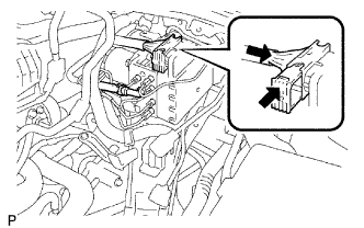
Release the lock and disconnect the brake actuator connector.
Remove the clip and disconnect the No. 2 brake actuator hose from the brake actuator.
![]() |
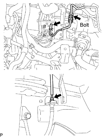
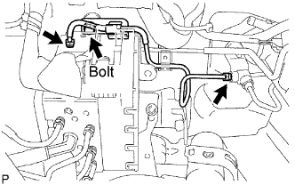
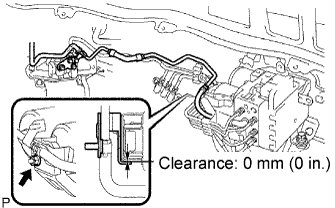
Using SST, disconnect the No. 5 front brake tube from the brake actuator and front brake flexible hose.
Remove the bolt and No. 5 front brake tube from the bracket of the brake actuator.
![]() |
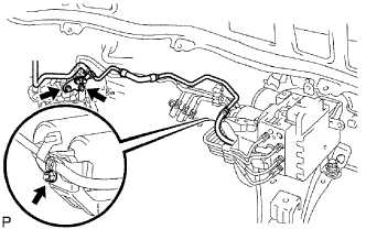
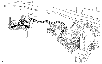
Using SST, disconnect the No. 1 front brake tube.
Remove the bolt and No. 1 front brake tube from the bracket of the brake actuator.
![]() |
Remove the 3 nuts and brake actuator tubes from the brake stroke simulator cylinder and brake actuator.
![]() |
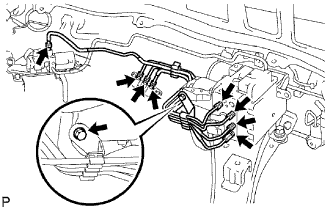
Remove the bolt from the brake actuator.
Using SST, remove the 4 brake tubes from the brake stroke simulator cylinder and brake actuator.
![]() |
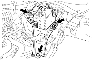
Remove the bolt, 2 nuts and brake actuator with gusset.
Remove the brake actuator.
![]() |
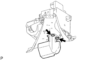
Remove the 2 bolts and brake actuator damper.
![]() |
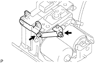
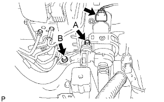
Remove the bolt, nut and bracket from the brake actuator.
![]() |
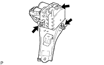
Remove the 2 nuts, bolt and brake actuator from the gusset.
![]() |
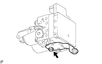
Remove the bolt and No. 2 brake actuator bracket from the brake actuator.
Install the brake actuator.
![]() |
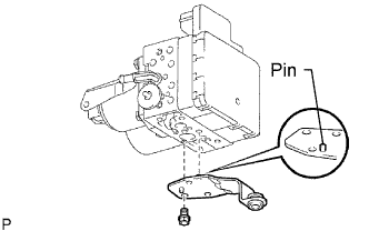
Aligning the positioning pin, install the No. 2 brake actuator bracket to the brake actuator with the bolt.
![]() |
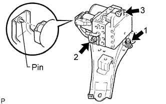
Aligning the positioning pin, install the brake actuator to the gusset with the 2 nuts and bolt.
![]() |
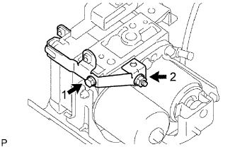
Install the bracket to the brake actuator with the bolt and nut.
![]() |
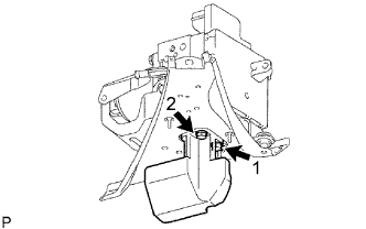
Install the brake actuator damper to the brake actuator with the 2 bolts.
Install the brake actuator with bracket.
![]() |
Install the brake actuator with gusset with the bolt and 2 nuts.
![]() |
Using SST, install the 4 brake tubes to the brake stroke simulator cylinder and brake actuator.
Set the brake tube with the clamp bracket bolt.
![]() |
Install the brake actuator tube with the 2 nuts.
![]() |
Set the brake actuator tube with the nut.
![]() |
Using SST, install the No. 1 front brake tube to the brake actuator and 2-way.
Install the No. 1 front brake tube to the bracket of the brake actuator with the bolt.
![]() |
Using SST, connect the No. 5 front brake tube.
Install the bracket of the No. 5 front brake tube with the bolt.
![]() |
Connect the brake actuator connector and fix it with the lock.
Install the No. 2 brake actuator hose to the brake actuator with the clip.
Connect the water pump with motor and bracket.
![]() |
Install the heater hose bracket to the gusset with the 2 clamps and bolt.
![]() |
Install the heater water pump with the 2 bolts.
Connect the heater water pump connector.
Install the inverter with converter (Click here).
Install the outer front cowl top panel .
Install the windshield wiper motor and link (Click here).
| 2. REPLACE BRAKE ACTUATOR RESISTOR |
Remove the instrument panel (Click here).
Remove the brake actuator resistor.
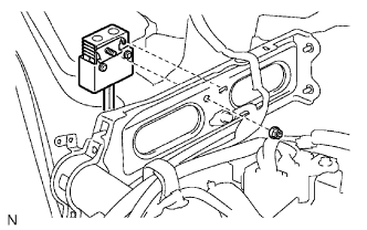
![]() |
Remove the nut.
Disconnect the connector and remove the resistor.
Install the brake actuator resistor.
![]() |
Connect the connector and install the resistor.
Install the nut.
Install the instrument panel (Click here).
| 3. FILL RESERVOIR WITH BRAKE FLUID |
Add brake fluid into the reservoir.
| 4. BLEED AIR FROM BRAKE ACTUATOR |
Bleed the air out of the FR/FL wheels if the display appears.
Bleed the air out of the drain line.
Depress the brake pedal 30 times within 30 seconds while the solenoid is operating.
Install the No. 1 and No. 2 motor relays.
Bleed the air out of the rear brake RL wheel.
Bleed the air out of the rear brake RR wheel.
Loosen the bleeder plug of FL wheel.
Bleed the air out of the power supply line.
Tighten the bleeder plug of FL wheel.
Bleed the air out of the stroke simulator line.
Depress the brake pedal 20 times in 20 seconds.
Perform the usual air bleeding for the FL wheel.
Refresh the high pressure line.
Turn the power switch OFF. Turn the power switch ON (IG) and check if the ABS motor pump runs and stops.
Return to "MENU".
| 5. CHECK FOR BRAKE FLUID LEAKAGE |
| 6. CHECK FLUID LEVEL IN RESERVOIR |
| 7. CHECK AND CLEAR DTC |
Check and clear the DTC (Click here).
| 8. PERFORM INITIALIZATION |
Perform initialization (Click here).
| 9. PERFORM SYSTEM INITIALIZATION |
Perform the brake system initialization (Click here).
| 10. PERFORM ACTIVE TEST |
Perform the Active Test (Click here).