BRAKE SYSTEM (OTHER) BRAKE BOOSTER(for LHD) INSTALLATION
PROCEDURE

 44785C
1.INSTALL BRAKE BOOSTER GASKET
Install a new brake booster gasket to the brake booster with master cylinder assembly.
47210L
2.INSTALL BRAKE BOOSTER WITH MASTER CYLINDER ASSEMBLY
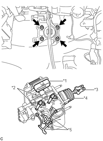
Install the brake booster with master cylinder assembly with the 4 nuts.
| *1 | Connector Portion |
| *2 | Union |
| *3 | Push Rod Clevis |
| *4 | Boot |
| *5 | Front No. 2 Brake Tube |
- Torque:
- 9.0 N*m (92 kgf*cm, 80 in.*lbf)
- NOTICE:
- ·
Do not kink or damage the brake lines.
·Do not carry the brake booster with master cylinder assembly by the portion shown in bold in the illustration.
·Be careful not to allow brake fluid to enter the connector.
·If installing a new brake booster with master cylinder assembly, do not remove the hole plugs before connecting the brake lines because the brake booster with master cylinder is filled with brake fluid.
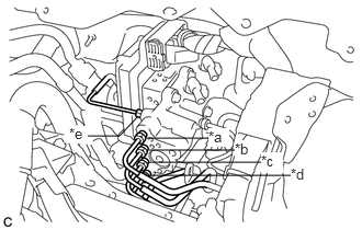
Temporarily tighten each brake line to the correct position on the brake booster with master cylinder assembly as shown in the illustration.
| *a | to Front Wheel Cylinder LH |
| *b | to Rear Wheel Cylinder RH |
| *c | to Brake Booster Pump Assembly |
| *d | to Rear Wheel Cylinder LH |
| *e | to Front Wheel Cylinder RH |
Using a union nut wrench, fully tighten each brake line.
- Torque:
- 15 N*m (155 kgf*cm, 11 ft.*lbf)
- NOTICE:
- ·
Do not kink or damage the brake lines.
·Use the formula to calculate special torque values for situations where the union nut wrench is combined with a torque wrench (See page General>INTRODUCTION>REPAIR INSTRUCTION>PRECAUTION).
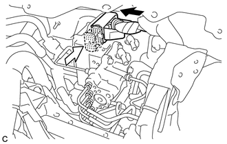
Connect the connector to the brake booster with master cylinder assembly.

|
Connect the connector |

|
Lock the lock lever |
- NOTICE:
- ·
Make sure that the connector can be connected smoothly. Do not allow foreign matter to enter.
·Make sure that the connector lock is locked securely.
47381N
3.INSTALL TUBE CLAMP BRACKET
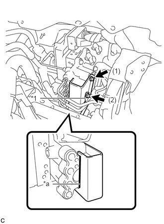
Temporarily install the tube clamp bracket to the brake booster with master cylinder assembly with the front No. 1 brake tube and 2 bolts.
| *1 | Front No. 1 Brake Tube |
| *a | The tube clamp bracket contacts the brake booster with master cylinder assembly. |
Tighten the 2 bolts in the order shown in the illustration.
- Torque:
- Bolt (1) : 8.0 N*m (82 kgf*cm, 71 in.*lbf)
- Bolt (2) : 7.0 N*m (71 kgf*cm, 62 in.*lbf)
- NOTICE:
-
When tightening the bolt (1), be sure that the tube clamp bracket contacts the brake booster with master cylinder assembly.
44571
4.CONNECT BRAKE ACTUATOR HOSE
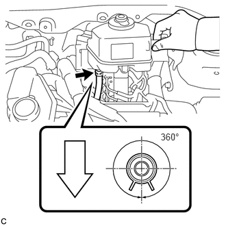
Connect the brake actuator hose to the brake master cylinder reservoir assembly with the clip.
|
|
Front of Vehicle |
- NOTICE:
- ·
Make sure that the identification mark on the brake actuator hose is positioned within 30° of the brake master cylinder reservoir assembly rib.
·Make sure to install the hose to the proper location.
·Install the clip within the range shown in the illustration.
47233
5.INSTALL RESERVOIR BRACKET
Install the reservoir bracket with the 2 bolts.
- Torque:
- 8.0 N*m (82 kgf*cm, 71 in.*lbf)
47234L
6.CONNECT NO. 1 RESERVOIR HOSE
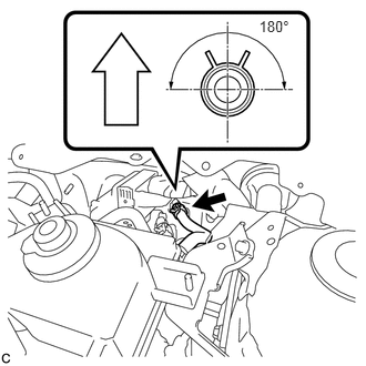
Connect the No. 1 reservoir hose to the brake booster with master cylinder assembly with the clip.
|
|
Up |
- NOTICE:
- ·
Make sure that the identification mark on the No. 1 reservoir hose is positioned within 30° of the brake booster with master cylinder assembly rib.
·When connecting the reservoir hose, face the identification mark up.
·Make sure to install the hose to the proper location.
·Install the clip within the range shown in the illustration.
47235G
7.CONNECT NO. 2 RESERVOIR HOSE
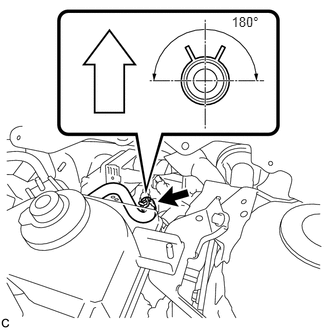
Connect the No. 2 reservoir hose to the brake booster with master cylinder assembly with the clip.
|
|
Up |
- NOTICE:
- ·
Make sure that the identification mark on the No. 2 reservoir hose is positioned within 30° of the brake booster with master cylinder assembly rib.
·When connecting the reservoir hose, face the identification mark up.
·Make sure to install the hose to the proper location.
·Install the clip within the range shown in the illustration.
47220D
8.INSTALL BRAKE MASTER CYLINDER RESERVOIR ASSEMBLY
Install the brake master cylinder reservoir assembly with the 2 nuts.
- Torque:
- 8.0 N*m (82 kgf*cm, 71 in.*lbf)
47264A
9.INSTALL PUSH ROD PIN
47101A
10.INSTALL BRAKE PEDAL RETURN SPRING
11.FILL RESERVOIR WITH BRAKE FLUID
12.CONNECT CABLE TO NEGATIVE AUXILIARY BATTERY TERMINAL
13.BLEED BRAKE SYSTEM
14.INSPECT AND ADJUST BRAKE PEDAL
15. OBTAIN ZERO POINT OF YAW RATE AND ACCELERATION SENSOR
- HINT:
-
After the brake booster with master cylinder assembly is replaced, obtain the zero point of the yaw rate and acceleration sensor (See page Brake>BRAKE CONTROL / DYNAMIC CONTROL SYSTEMS>ELECTRONICALLY CONTROLLED BRAKE SYSTEM>CALIBRATION).
55701J
16.INSTALL OUTER COWL TOP PANEL SUB-ASSEMBLY
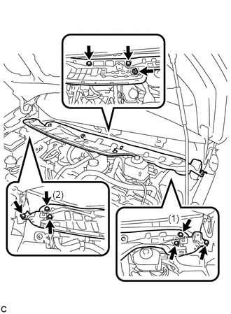
Install the outer cowl top panel sub-assembly with the 8 bolts and nut.
- Torque:
- Bolt : 7.0 N*m (71 kgf*cm, 62 in.*lbf)
- Nut : 12 N*m (122 kgf*cm, 9 ft.*lbf)
- NOTICE:
-
Tighten the 2 bolts (1) and (2) first, and then tighten the rest of the bolts and nut.
Engage the clamp to install the wire harness.
55815E
17.INSTALL FRONT NO. 1 VENTILATOR SEAL
Engage the clamp to install the front No. 1 ventilator seal to the outer cowl top panel sub-assembly.
55735B
18.INSTALL FRONT AIR SHUTTER SEAL
Engage the clamp to install the front air shutter seal to the outer cowl top panel sub-assembly.
55722C
19.INSTALL INNER COWL TOP TO COWL BRACE
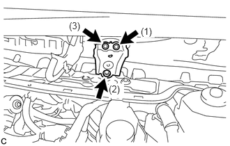
Install the inner cowl top to cowl brace to the outer cowl top panel sub-assembly with the 3 bolts.
- Torque:
- 7.0 N*m (71 kgf*cm, 62 in.*lbf)
- NOTICE:
-
Tighten the 3 bolts in the order shown in the illustration.
20.INSTALL WINDSHIELD WIPER MOTOR AND LINK ASSEMBLY