INTERIOR PANELS / TRIM LOWER INSTRUMENT PANEL REMOVAL
PROCEDURE

 1. PRECAUTION
2.REMOVE UPPER INSTRUMENT PANEL ASSEMBLY
55446A
3.REMOVE NO. 1 SWITCH HOLE BASE
for LHD:
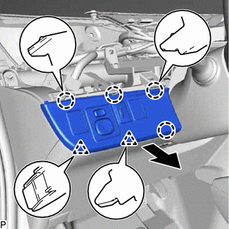
Disengage the 4 claws and 2 clips as shown in the illustration.
Disconnect each connector to remove the No. 1 switch hole base.
for RHD:
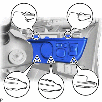
Disengage the 2 claws and 3 clips.
Disconnect each connector to remove the No. 1 switch hole base.
55433C
4.REMOVE LOWER INSTRUMENT PANEL FINISH PANEL LH (for LHD)
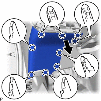
Disengage the 9 claws as shown in the illustration to remove the lower instrument panel finish panel LH.
45287
5.REMOVE LOWER STEERING COLUMN COVER
73900
6.REMOVE LOWER NO. 1 INSTRUMENT PANEL AIRBAG ASSEMBLY
55840C
7.REMOVE NO. 6 HEATER TO REGISTER DUCT ASSEMBLY
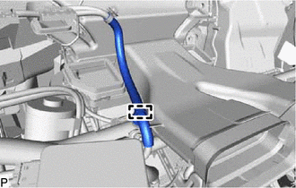
Disengage the clamp.
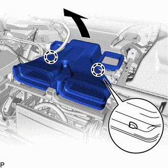
Disengage the 2 claws as shown in the illustration.
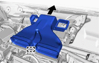
Disengage the guide as shown in the illustration to remove the No. 6 heater to register duct assembly.
8.REMOVE RADIO TUNER OPENING COVER WITH BRACKET (w/o Radio Receiver)
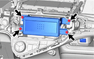
Remove the 4 screws <C> and radio tuner opening cover with bracket.
9.REMOVE RADIO RECEIVER ASSEMBLY WITH BRACKET (w/ Radio Receiver)
55479D
10.REMOVE LOWER INSTRUMENT CLUSTER FINISH PANEL GARNISH
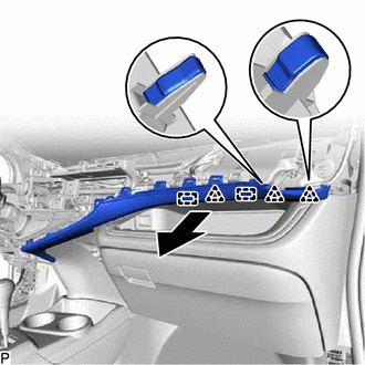
Disengage the 3 clips and 2 guides as shown in the illustration.
- NOTICE:
-
Do not forcibly pull the lower instrument cluster finish panel garnish as it may be damaged.
- HINT:
-
Disengage the clips and guides from the outerside first.
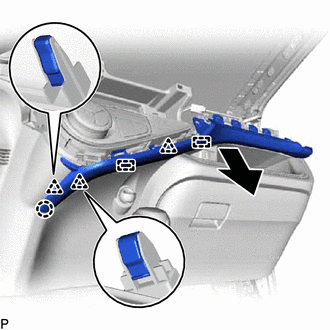
Disengage the claw, 3 clips and 2 guides as shown in the illustration.
- NOTICE:
-
Do not forcibly pull the lower instrument cluster finish panel garnish as it may be damaged.
- HINT:
-
If the clips, claw and guides are difficult to disengage, use a moulding remover.
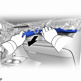
Disengage the claw as shown in the illustration to remove the lower instrument cluster finish panel garnish.
- NOTICE:
-
Do not forcibly pull the lower instrument cluster finish panel garnish as it may be damaged.
- HINT:
-
If the claw is difficult to disengage, use a moulding remover.
55900
11.REMOVE AIR CONDITIONING CONTROL ASSEMBLY
88625Q
12.REMOVE ROOM TEMPERATURE SENSOR (COOLER THERMISTOR)
58917A
13.REMOVE REAR CONSOLE BOX COVER
58821C
14.REMOVE UPPER CONSOLE PANEL
58811A
15.REMOVE FRONT CONSOLE BOX
58919B
16.REMOVE CONSOLE BOX PLATE
17.REMOVE REAR CONSOLE BOX ASSEMBLY
55440D
18.REMOVE INSTRUMENT PANEL BOX ASSEMBLY
for LHD:
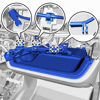
Disengage the 3 clamps.
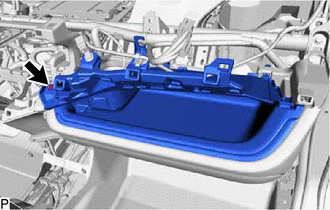
Remove the screw <D>.
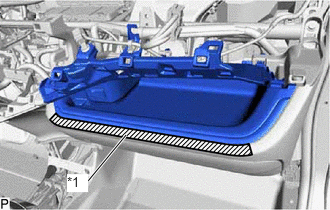
Apply protective tape to the area shown in the illustration.
| *1 | Protective Tape |
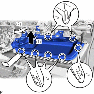
Using a moulding remover, pull the instrument panel box in the direction indicated by the arrow (1) to disengage the 5 claws (A).
| *a | Claw (A) |
| *b | Claw (B) |
Pull the instrument panel box in the direction indicated by the arrow (2) to disengage the 2 claws (B) and remove the instrument panel box assembly.
55550
19.REMOVE GLOVE COMPARTMENT DOOR ASSEMBLY
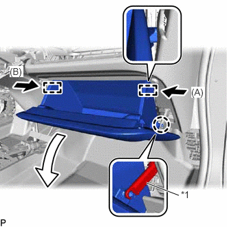
Disengage the claw to disconnect the glove compartment door stopper sub-assembly.
| *1 | Glove Compartment Door Stopper Sub-assembly |
Slightly bend the stopper (A) and (B) in the directions indicated by the arrows in the illustration and open the glove compartment door assembly until the stoppers are released.
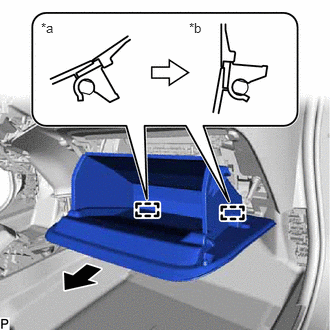
Open the glove compartment door assembly to approximately 55° from its closed position. Pull it horizontally in the direction indicated by the arrow to disengage the 2 hinges and remove the glove compartment door assembly.
| *a | Closed |
| *b | Open Approximately 55° |
- NOTICE:
-
Pulling the glove compartment door assembly upward to remove it causes the hinges to deform. Be sure to pull out the glove compartment door assembly horizontally.
67914
20.REMOVE FRONT DOOR SCUFF PLATE LH
62112
21.REMOVE COWL SIDE TRIM BOARD LH
67913
22.REMOVE FRONT DOOR SCUFF PLATE RH
- HINT:
-
Use the same procedure as for the LH side.
62111C
23.REMOVE COWL SIDE TRIM BOARD RH
- HINT:
-
Use the same procedure as for the LH side.
53601
24.DISCONNECT HOOD LOCK CONTROL LEVER SUB-ASSEMBLY
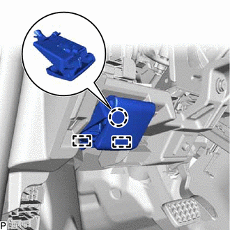
Disengage the claw and 2 guides and disconnect the hood lock control lever sub-assembly.
25.REMOVE LOWER INSTRUMENT PANEL SUB-ASSEMBLY (for LHD)
Disengage each clamp.
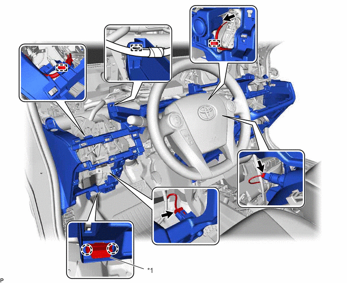
| *1 | DLC3 | - | - |
Disconnect each connector.
Disengage the 2 claws to disconnect the DLC3.
Remove the 2 bolts <A>, 7 screws <C> and screw <B> and lower instrument panel sub-assembly.
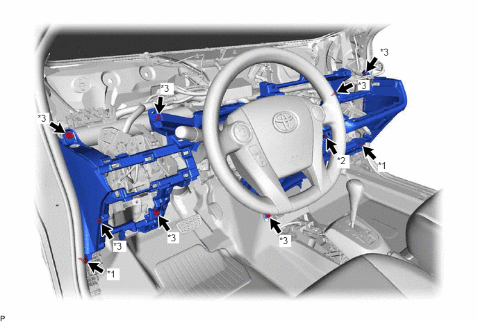
| *1 | Bolt <A> | *2 | Screw <B> |
| *3 | Screw <C> | - | - |
26.REMOVE LOWER INSTRUMENT PANEL SUB-ASSEMBLY (for RHD)
Disengage each clamp.
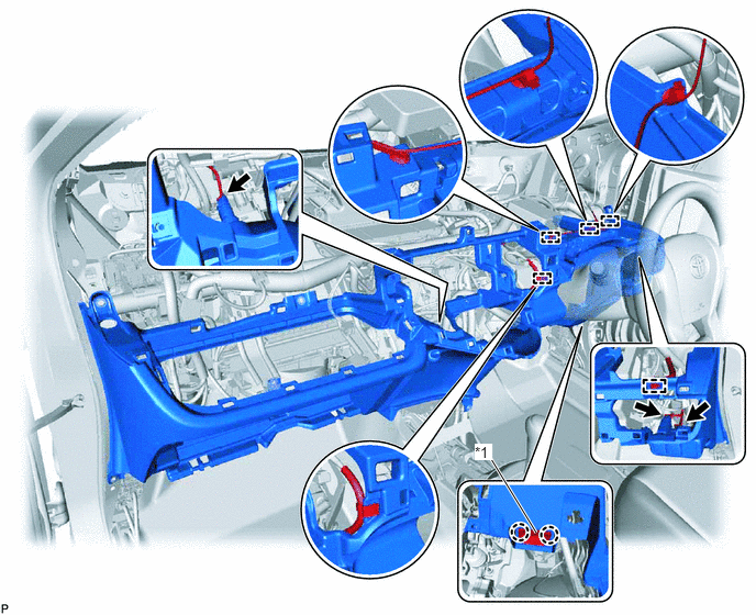
| *1 | DLC3 | - | - |
Disconnect each connector.
Disengage the 2 claws to disconnect the DLC3.
Remove the 2 bolts <A>, 7 screws <C> and screw <B> and lower instrument panel sub-assembly.
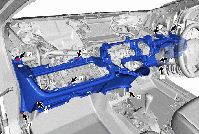
| *1 | Bolt <A> | *2 | Screw <B> |
| *3 | Screw <C> | - | - |