1NZ-FXE COOLING RADIATOR INSTALLATION
PROCEDURE

 16400
1.INSTALL RADIATOR ASSEMBLY
Install the radiator assembly with the 2 claws.
Install the No. 3 radiator hose with the 2 bolts.
- Torque:
- 7.5 N*m (76 kgf*cm, 66 in.*lbf)
Install the 2 lower radiator supports.
Install the radiator assembly with the fan shroud.
- NOTICE:
-
Do not apply any excessive force to the cooler condenser assembly or pipe when installing the radiator assembly.
16712
2.INSTALL NO. 2 FAN SHROUD
Install the No. 2 fan shroud with the 2 bolts and 2 claws.
- Torque:
- 7.0 N*m (71 kgf*cm, 62 in.*lbf)
53205
3.INSTALL UPPER RADIATOR SUPPORT SUB-ASSEMBLY
Install the 2 radiator support cushions.
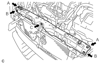
Temporarily install the upper radiator support sub-assembly with the 5 bolts.
Fully tighten the bolt (A).
- Torque:
- 5.5 N*m (56 kgf*cm, 49 in.*lbf)
Fully tighten the bolt (B).
- Torque:
- 5.5 N*m (56 kgf*cm, 49 in.*lbf)
Fully tighten the bolt (C).
- Torque:
- 13 N*m (127 kgf*cm, 9 ft.*lbf)
Connect the clamp of the hood lock control cable.
Connect the cooling fan ECU connector and 3 clamps.
Connect the horn connector.
G90A0A
4.CONNECT NO. 1 INVERTER COOLING HOSE ASSEMBLY
Connect the No. 1 inverter cooling hose assembly and 3 clamps.
G922F
5.CONNECT OUTLET NO. 1 HYBRID WATER PUMP HOSE
Connect the outlet No. 1 hybrid water pump hose and 3 clamps.
16572D
6.CONNECT NO. 2 RADIATOR HOSE
Connect the No. 2 radiator hose.
16571C
7.CONNECT NO. 1 RADIATOR HOSE
Connect the No. 1 radiator hose.
Connect the reserve tank hose.
53510
8.INSTALL HOOD LOCK ASSEMBLY
9.INSTALL AIR CLEANER CASE SUB-ASSEMBLY
17705
10.INSTALL AIR CLEANER CAP SUB-ASSEMBLY
53289A
11.INSTALL RADIATOR SUPPORT OPENING COVER
12.INSTALL FRONT BUMPER ASSEMBLY
13.CONNECT CABLE TO NEGATIVE AUXILIARY BATTERY TERMINAL
- NOTICE:
-
When disconnecting the cable, some systems need to be initialized after the cable is reconnected (See page General>INTRODUCTION>REPAIR INSTRUCTION>INITIALIZATION).
58165F
14.INSTALL FRONT FLOOR COVER RH
15.ADD COOLANT (for Inverter)
16.ADD COOLANT (for Engine)
17.INSPECT FOR COOLANT LEAK (for Inverter)
18.INSPECT FOR COOLANT LEAK (for Engine)
51441C
19.INSTALL ENGINE UNDER COVER RH (Separated Cover Type)
51442C
20.INSTALL ENGINE UNDER COVER LH (Separated Cover Type)
21.INSTALL NO. 1 ENGINE UNDER COVER ASSEMBLY (Integrated Cover Type)