2005-2008 RAV4 · Service Manual DRIVE LINE

REPLACEMENT

Removal / installation · Vehicles built Nov 2005 – Dec 2006

Versions by build date: Nov 2005 – Dec 2006 Jan 2007 – Jul 2007 from Aug 2007


1. DISCONNECT CABLE FROM NEGATIVE BATTERY TERMINAL

CAUTION:
Wait at least 90 seconds after disconnecting the cable from the negative (-) battery terminal to prevent airbag and seat belt pretensioner activation.


2. DRAIN AUTOMATIC TRANSAXLE FLUID
  1. Remove the drain plug and gasket, and drain ATF.

  1. Install a new gasket and drain plug.

    Torque:
    47 N*m{ 479 kgf*cm , 35 ft.*lbf }


3. DRAIN TRANSAXLE OIL
  1. Remove the filler plug and gasket.

  1. Remove the drain plug and gasket, and drain the oil.

  1. Install a new gasket and the drain plug.

    Torque:
    39 N*m{ 398 kgf*cm , 28 ft.*lbf }


4. DRAIN TRANSFER OIL
  1. Remove the drain plug and gasket, and drain the oil.

  1. Install a new gasket and drain plug.

    Torque:
    39 N*m{ 398 kgf*cm , 28 ft.*lbf }


5. REMOVE PROPELLER WITH CENTER BEARING SHAFT ASSEMBLY

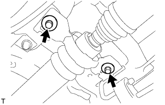
  1. C127524
    Remove the 2 bolts and 2 adjusting washers, and disconnect the propeller with center bearing shaft.

    NOTICE:
    1. During the removal, do not exert excessive force on the universal joint.
    2. When removing, transporting or storing the propeller with center bearing shaft assembly, do not allow the No. 2 joint angle to exceed 20°.

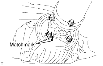
  1. C127525E01
    Place matchmarks on the differential carrier and propeller shaft.

  1. Remove the 4 nuts and 4 washers, and disconnect the propeller shaft and differential carrier.

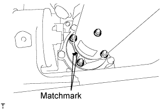
  1. C127526E01
    Place matchmarks on the transfer and propeller shaft.

  1. Remove the 4 nuts and 4 washers, and disconnect the propeller shaft from the transfer.


6. REMOVE ENGINE ASSEMBLY WITH TRANSAXLE
  1. for 1AZ-FE:
    Remove the engine with transaxle (Click here).

  1. for 2AZ-FE:
    Remove the engine with transaxle (Click here).

  1. for 2AD-FTV:
    Remove the engine with transaxle (Click here).

  1. for 2AD-FHV:
    Remove the engine with transaxle (Click here).


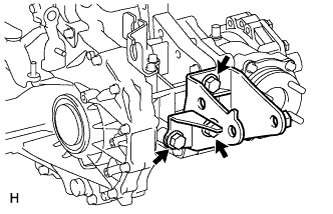
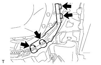
7. REMOVE REAR ENGINE MOUNTING BRACKET

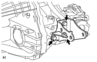
  1. C130624
    for U140F:
    Remove the 3 bolts and mounting bracket.

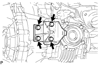
  1. C130625
    for E352F/359F:
    Remove the 3 bolts and mounting bracket.

  1. C129379
    for EA64F:
    Remove the 4 bolts and mounting bracket.


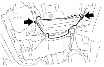
8. REMOVE FLYWHEEL HOUSING UNDER COVER (for Manual Transaxle)

C127239
  1. Remove the 2 bolts and under cover from the stiffener plate.


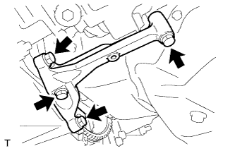
9. REMOVE STIFFENER PLATE LH (for Manual Transaxle)

C127240
  1. Remove the 4 bolts and stiffener plate from the engine and transaxle.


10. REMOVE STIFFENER PLATE RH (for Manual Transaxle)

C127241
  1. Remove the 4 bolts and stiffener plate from the engine and transaxle.


11. REMOVE AUTOMATIC TRANSAXLE ASSEMBLY (for U140F)
  1. Remove the automatic transaxle (Click here).


12. REMOVE MANUAL TRANSAXLE ASSEMBLY (for E352F/E359F)
  1. Remove manual transaxle (Click here).


13. REMOVE MANUAL TRANSAXLE ASSEMBLY (for EA64F)
  1. Remove manual transaxle (Click here).


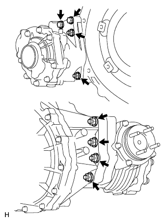
14. REMOVE TRANSFER ASSEMBLY

C126622
  1. Remove the 2 bolts, 6 nuts and transfer from the manual transaxle.


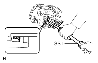
15. REMOVE TRANSFER CASE OIL SEAL

C126623E01
  1. Using SST, tap out the transfer case oil seal.

    SST
    09308-00010  


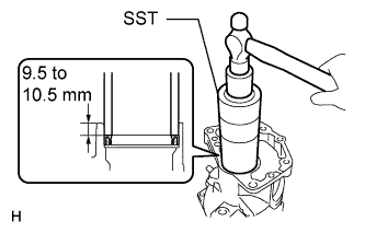
16. INSTALL TRANSFER CASE OIL SEAL

C126624E01
  1. Coat a new oil seal lip with MP grease.

  1. Using SST and a hammer, tap in the transfer case oil seal.

    SST
    09316-60011   (09316-00011)

    Standard depth:
    9.5 to 10.5 mm (0.37 to 0.41 in.)

    NOTICE:
    Do not damage the oil seal lip.


17. INSTALL TRANSFER ASSEMBLY

C126622
  1. Install the transfer with the 6 nuts and 2 bolts.

    Torque:
    69 N*m{ 700 kgf*cm , 51 ft.*lbf }


18. INSTALL AUTOMATIC TRANSAXLE ASSEMBLY (for U140F)
  1. Install automatic transaxle (Click here).


19. INSTALL MANUAL TRANSAXLE ASSEMBLY (for E352F/E359F)
  1. Install manual transaxle (Click here).


20. INSTALL MANUAL TRANSAXLE ASSEMBLY (for EA64F)
  1. Install manual transaxle (Click here).


21. INSTALL STIFFENER PLATE RH (for Manual Transaxle)

C127241
  1. Install the stiffener plate with the 4 bolts.

    Torque:
    46 N*m{ 469 kgf*cm , 34 ft.*lbf }


22. INSTALL STIFFENER PLATE LH (for Manual Transaxle)

C127240
  1. Install the stiffener plate with the 4 bolts.

    Torque:
    46 N*m{ 469 kgf*cm , 34 ft.*lbf }


23. INSTALL FLYWHEEL HOUSING UNDER COVER (for Manual Transaxle)

C127239
  1. Install the cover with the 2 bolts.

    Torque:
    9.0 N*m{ 92 kgf*cm , 80 in.*lbf }


24. INSTALL REAR ENGINE MOUNTING BRACKET

  1. C130624
    for U140F:
    Install the mounting bracket with the 3 bolts.

    Torque:
    45 N*m{ 459 kgf*cm , 33 ft.*lbf }

  1. C130625
    for E352F/E359F:
    Install the mounting bracket with the 3 bolts.

    Torque:
    45 N*m{ 459 kgf*cm , 33 ft.*lbf }

  1. C129379
    for EA64F:
    Install the mounting bracket with the 4 bolts.

    Torque:
    45 N*m{ 459 kgf*cm , 33 ft.*lbf }


25. INSTALL TRANSAXLE WITH ENGINE ASSEMBLY
  1. for 1AZ-FE:
    Install the transaxle with engine (Click here).

  1. for 2AZ-FE:
    Install the transaxle with engine (Click here).

  1. for 2AD-FTV:
    Install the transaxle with engine (Click here).

  1. for 2AD-FHV:
    Install the transaxle with engine (Click here).


26. INSTALL PROPELLER WITH CENTER BEARING SHAFT ASSEMBLY

  1. C127526E01
    Align the matchmarks of the transfer and propeller shaft.

  1. Temporarily install the propeller shaft with center bearing with the 4 nuts and 4 washers.

  1. C127525E01
    Align the matchmarks of the differential carrier and propeller shaft.

  1. Temporarily install the propeller shaft with center bearing with the 4 bolts and 4 washers.

  1. C127524
    Temporarily install the center support bearing and center support bearing washer with the 2 bolts.


27. ADD AUTOMATIC TRANSAXLE FLUID

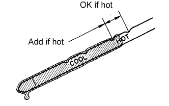
28. INSPECT AUTOMATIC TRANSAXLE FLUID

HINT:
Drive the vehicle so that the engine and transaxle are at normal operating temperature.

Fluid temperature:
70 to 80°C (158 to 176°F)

  1. D025120E03
    Park the vehicle on a level surface and set the parking brake.

  1. With the engine idling and the brake pedal depressed, move the shift lever to each position from P to L position, and return it to the P position.

  1. Take out the ATF dipstick and wipe it clean.

  1. Fully push the dipstick back into the pipe.

  1. Take it out and check that the fluid level is at the HOT position.
    If there are leaks, it is necessary to repair or replace O-rings, FIPGs, oil seals, plugs and/or other parts.


29. ADD TRANSAXLE OIL

30. INSPECT TRANSAXLE OIL
  1. for E352F/E359F:
    Inspect transaxle oil (Click here).

  1. for EA64F:
    Inspect transaxle oil (Click here).


31. ADD TRANSFER OIL

32. INSPECT TRANSFER OIL

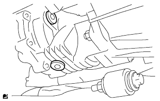
  1. C110905
    Remove the transfer case plug No. 2 (for filler) and gasket.

  1. Check that the oil level is between 0 to 5.0 mm (0 to 0.20 in.) from the bottom lip of the case plug (for filler) hole.
    If the result is not as specified, add transfer oil.

    Oil grade:
    GL-5

    Viscosity:
    SAE 80W-90

    Standard capacity:
    0.45 liter (0.48 US qts, 0.40 Imp. qts)

    NOTICE:
    1. When adding oil, pour it slowly.
    2. Too much or too little oil will lead to transfer problems.

  1. When the oil level is too low, check for oil leakage.

  1. Install a new gasket into the case plug (for filler) and then tighten the plug.

    Torque:
    39 N*m{ 398 kgf*cm , 28 ft.*lbf }


33. CONNECT CABLE TO NEGATIVE BATTERY TERMINAL

34. INSPECT SRS WARNING LIGHT
  1. Check the SRS warning light (Click here).

← COMPONENTS (from Aug 2007)REPLACEMENT (Jan 2007 – Jul 2007) →