3ZR-FE LUBRICATION OIL PUMP REMOVAL
PROCEDURE

 1.REMOVE ENGINE ASSEMBLY WITH TRANSAXLE
2.INSTALL ENGINE TO ENGINE STAND
22210
3.REMOVE THROTTLE BODY ASSEMBLY
25719
4.REMOVE VACUUM SURGE TANK
5.REMOVE INTAKE MANIFOLD
23901
6.REMOVE FUEL TUBE SUB-ASSEMBLY
23807
7.REMOVE FUEL DELIVERY PIPE SUB-ASSEMBLY
23250
8.REMOVE FUEL INJECTOR ASSEMBLY
19500
9.REMOVE IGNITION COIL ASSEMBLY
11452
10.REMOVE ENGINE OIL LEVEL DIPSTICK GUIDE
17167
11.REMOVE NO. 1 EXHAUST MANIFOLD HEAT INSULATOR
17118
12.REMOVE MANIFOLD STAY
17141
13.REMOVE EXHAUST MANIFOLD
12261
14.REMOVE PCV HOSE
16267
15.DISCONNECT NO. 3 WATER BY-PASS HOSE
16268
16.REMOVE NO. 1 WATER BY-PASS PIPE
17.REMOVE WATER BY-PASS HOSE
16262
18.DISCONNECT WATER INLET HOSE
16321
19.REMOVE WATER INLET
16331A
20.REMOVE THERMOSTAT
11201
21.REMOVE CYLINDER HEAD COVER SUB-ASSEMBLY
11213
22.REMOVE CYLINDER HEAD COVER GASKET
23.SET NO. 1 CYLINDER TO TDC/COMPRESSION
13471
24.REMOVE CRANKSHAFT PULLEY
13540
25.REMOVE NO. 1 CHAIN TENSIONER ASSEMBLY
26.REMOVE OIL FILTER
27.REMOVE ENGINE MOUNTING BRACKET STUD BOLT
11302
28.REMOVE TIMING CHAIN COVER SUB-ASSEMBLY
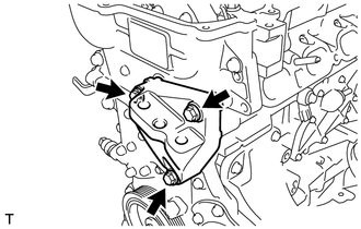
Remove the 3 bolts and engine mounting bracket RH.
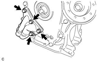
Remove the 4 bolts and oil filter bracket.
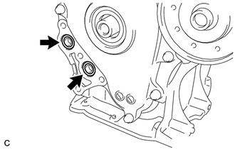
Remove the 2 O-rings.
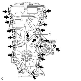
| *1 | Seal Washer |
Remove the 19 bolts and seal washer.
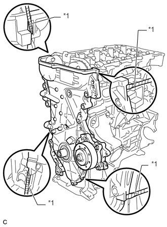
| *1 | Protective Tape |
Remove the timing chain cover sub-assembly by prying between the timing chain cover sub-assembly and cylinder head, camshaft housing, cylinder block and stiffening crankcase with a screwdriver as shown in the illustration.
- NOTICE:
-
Be careful not to damage the contact surfaces of the cylinder head, camshaft housing, cylinder block, stiffening crankcase and timing chain cover sub-assembly.
- HINT:
-
Tape the screwdriver tip before use.
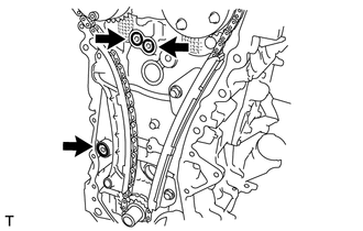
Remove the 3 O-rings.
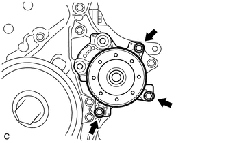
Remove the 3 bolts and engine water pump assembly.
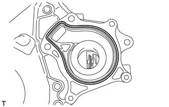
Remove the gasket.
11302A
29.REMOVE TIMING CHAIN COVER OIL SEAL
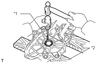
| *1 | Protective Tape |
| *2 | Wooden Block |
Place the timing chain cover on wooden blocks.
Using a screwdriver, tap out the timing chain cover oil seal.
- NOTICE:
-
Do not damage the surface of the oil seal press fit hole.
- HINT:
-
Tape the screwdriver tip before use.
13559
30.REMOVE CHAIN TENSIONER SLIPPER
13561
31.REMOVE NO. 1 CHAIN VIBRATION DAMPER
13562
32.REMOVE NO. 2 CHAIN VIBRATION DAMPER
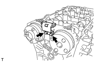
Remove the 2 bolts and No. 2 chain vibration damper.
13506
33.REMOVE CHAIN SUB-ASSEMBLY
13521
34.REMOVE CRANKSHAFT TIMING SPROCKET
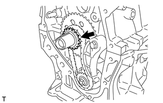
Remove the crankshaft timing sprocket.
13507
35.REMOVE NO. 2 CHAIN SUB-ASSEMBLY
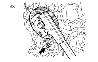
Temporarily install the crankshaft pulley and crankshaft pulley bolt.
Using SST, hold the crankshaft. Then remove the drive shaft gear nut.
for 86 mm (3.39 in.) Bolt Pitch Type:
- SST
- 09213-58014 (91551-80840)
09330-00021
for 64 mm (2.52 in.) Bolt Pitch Type:
- SST
- 09213-54015 09330-00021
- HINT:
-
For the 64 mm (2.52 in.) bolt pitch type, the part number of the installationbolt for SST (crankshaft pulley holding tool) is 91551-00850 (quantity: 2).
Remove SST, the crankshaft pulley bolt and the crankshaft pulley.
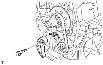
Remove the bolt, chain tensioner plate and chain damper spring.
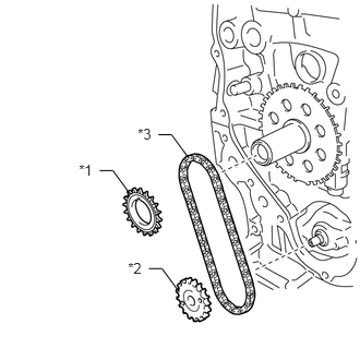
| *1 | Oil Pump Drive Gear |
| *2 | Oil Pump Drive Shaft Gear |
| *3 | No. 2 Chain Sub-assembly |
Remove the oil pump drive gear, oil pump drive shaft gear and No. 2 chain.
12102A
36.REMOVE NO. 2 OIL PAN SUB-ASSEMBLY
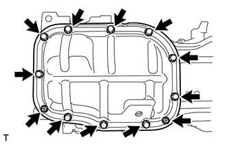
Remove the 10 bolts and 2 nuts.
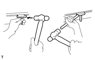
Insert the blade of an oil pan seal cutter between the stiffening crankcase and No. 2 oil pan sub-assembly. Cut through the sealer and remove the No. 2 oil pan sub-assembly.
- NOTICE:
- ·
Be careful not to damage the surface of the No. 2 oil pan sub-assembly which contacts the stiffening crankcase.
·Be careful not to damage the stiffening crankcase flange.
15100
37.REMOVE OIL PUMP ASSEMBLY
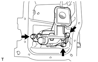
Remove the 3 bolts and oil pump assembly.