DRIVE SHAFT / PROPELLER SHAFT FRONT DRIVE SHAFT ASSEMBLY(for 2WD) INSTALLATION
PROCEDURE

 43420G
1.INSTALL FRONT DRIVE SHAFT HOLE SNAP RING LH
Install a new front drive shaft hole snap ring LH.
- NOTICE:
- ·
Do not damage the spline of the front drive inboard joint assembly LH.
·Front drive shaft hole snap ring LH should be installed completely.
43420
2.INSTALL FRONT DRIVE SHAFT ASSEMBLY LH
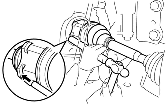
Coat the spline of the front drive inboard joint assembly LH with MP grease.
Set the front drive shaft hole snap ring LH with the opening side facing down.
Align the splines and tap in the front drive shaft assembly LH with a brass bar and hammer.
- NOTICE:
- ·
Using MP grease, set the front drive shaft hole snap ring in the groove with the opening facing downwards and centered radially.
·Do not damage the oil seal, front axle inboard joint boot and front drive shaft dust cover LH.
·Make sure to follow the proper handling and installation procedures. If the front drive shaft assembly LH is installed at too large an angle or slides too much, it may fall out of the groove of the tripod joint.
·Do not tap the end of the front drive outboard joint shaft assembly LH with a hammer, etc.
- HINT:
-
Determine whether the front drive shaft assembly LH is completely tapped in by checking for changes in the tapping sound or the reaction of the brass bar.
43410
3.INSTALL FRONT DRIVE SHAFT ASSEMBLY RH
w/o Drive Shaft Bearing Case:
Install a new drive shaft bearing bracket hole snap ring to the front drive shaft assembly RH.
Align the shaft splines and securely install the front drive shaft assembly RH.
- NOTICE:
- ·
Do not damage the transaxle case oil seal, front axle inboard joint boot and front drive shaft dust cover RH.
·Make sure to follow the proper handling and installation procedures. If the front drive shaft assembly RH is installed at too large an angle or slides too much, it may fall out of the groove of the tripod joint.
·Do not tap the end of the front drive outboard joint shaft assembly RH with a hammer, etc.
Install the drive shaft bearing bracket hole snap ring and a new bolt.
- Torque:
- 32.4 N*m (330 kgf*cm, 24 ft.*lbf)
- NOTICE:
-
Before installing the bolt, check the end for rubber.
w/ Drive Shaft Bearing Case:
Align the shaft splines and securely install the front drive shaft assembly RH.
for 2AR-FE, 3ZR-FE:
Install the front drive shaft assembly RH with the 2 bolts.
- Torque:
- 50.5 N*m (515 kgf*cm, 37 ft.*lbf)
- NOTICE:
- ·
Do not damage the transaxle case oil seal, front axle inboard joint boot and front drive shaft dust cover RH.
·Make sure to follow the proper handling and installation procedures. If the front drive shaft assembly RH is installed at too large an angle or slides too much, it may fall out of the groove of the tripod joint.
·Do not tap the end of the front drive outboard joint shaft assembly RH with a hammer, etc.
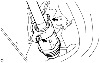
for 2WW:
Using a T50 ''TORX'' socket wrench, after temporarily installing bolt A, tighten the 2 bolts in the order A, B.
- Torque:
- 63.7 N*m (650 kgf*cm, 47 ft.*lbf)
- NOTICE:
- ·
Do not damage the transaxle case oil seal, front axle inboard joint boot and front drive shaft dust cover RH.
·Make sure to follow the proper handling and installation procedures. If the front drive shaft assembly RH is installed at too large an angle or slides too much, it may fall out of the groove of the tripod joint.
·Do not tap the end of the front drive outboard joint shaft assembly RH with a hammer, etc.
4.CONNECT STEERING KNUCKLE WITH AXLE HUB LH
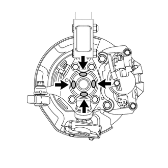
Apply MP grease to the entire contact surface between the front drive shaft assembly and axle hub bearing surface or only apply 0.1 to 0.3 g (0.00353 to 0.0105 oz.) of MP grease to the 4 areas on the axle hub bearing shown in the illustration.
Align the matchmarks and connect the steering knuckle with axle hub LH.
- NOTICE:
- ·
Do not damage the dust deflector.
·Do not damage the front axle outboard joint boot.
·Do not press the front axle assembly LH more than necessary.
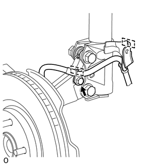
Attach the 2 guides and install the bolt.
- Torque:
- 29 N*m (296 kgf*cm, 21 ft.*lbf)
5.CONNECT STEERING KNUCKLE WITH AXLE HUB RH
- HINT:
-
Use the same procedure described for the LH side.
48069
6.CONNECT FRONT LOWER NO. 1 SUSPENSION ARM SUB-ASSEMBLY LH
48068
7.CONNECT FRONT LOWER NO. 1 SUSPENSION ARM SUB-ASSEMBLY RH
- HINT:
-
Use the same procedure described for the LH side.
48810
8.INSTALL FRONT STABILIZER LINK ASSEMBLY LH
48820B
9.INSTALL FRONT STABILIZER LINK ASSEMBLY RH
- HINT:
-
Use the same procedure described for the LH side.
10.CONNECT FRONT SPEED SENSOR LH
11.CONNECT FRONT SPEED SENSOR RH
- HINT:
-
Use the same procedure described for the LH side.
43502H
12.INSTALL FRONT AXLE SHAFT NUT LH
43501H
13.INSTALL FRONT AXLE SHAFT NUT RH
- HINT:
-
Use the same procedure described for the LH side.
14.ADD AUTOMATIC TRANSAXLE FLUID
15.ADD MANUAL TRANSAXLE OIL
for EA64: (Click hereDrivetrain>EA64 MANUAL TRANSMISSION / TRANSAXLE>MANUAL TRANSAXLE OIL>REPLACEMENT)
for EB61: (Click hereDrivetrain>EB61 MANUAL TRANSMISSION / TRANSAXLE>MANUAL TRANSAXLE OIL>REPLACEMENT)
for EB63: (Click hereDrivetrain>EB63 MANUAL TRANSMISSION / TRANSAXLE>MANUAL TRANSAXLE OIL>REPLACEMENT)
16.ADD CONTINUOUSLY VARIABLE TRANSAXLE FLUID
for K111: (Click hereDrivetrain>K111 MULTIDRIVE / CVT>CONTINUOUSLY VARIABLE TRANSAXLE FLUID>ADJUSTMENT)
for K114: (Click hereDrivetrain>K114 MULTIDRIVE / CVT>CONTINUOUSLY VARIABLE TRANSAXLE FLUID>ADJUSTMENT)
17.INSPECT FOR OIL LEAK
51443
18.INSTALL REAR ENGINE UNDER COVER RH
for 2WW: (Click hereEngine / Hybrid System>2WW ENGINE MECHANICAL>ENGINE ASSEMBLY>INSTALLATION)
for 2AR-FE: (Click hereEngine / Hybrid System>2AR-FE ENGINE MECHANICAL>ENGINE ASSEMBLY>INSTALLATION)
for 3ZR-FE: (Click hereEngine / Hybrid System>3ZR-FE ENGINE MECHANICAL>ENGINE ASSEMBLY>INSTALLATION)
51444C
19.INSTALL REAR ENGINE UNDER COVER LH
for 2WW: (Click hereEngine / Hybrid System>2WW ENGINE MECHANICAL>ENGINE ASSEMBLY>INSTALLATION)
for 2AR-FE: (Click hereEngine / Hybrid System>2AR-FE ENGINE MECHANICAL>ENGINE ASSEMBLY>INSTALLATION)
for 3ZR-FE: (Click hereEngine / Hybrid System>3ZR-FE ENGINE MECHANICAL>ENGINE ASSEMBLY>INSTALLATION)
51441
20.INSTALL NO. 1 ENGINE UNDER COVER
for 2WW: (Click hereEngine / Hybrid System>2WW ENGINE MECHANICAL>ENGINE ASSEMBLY>INSTALLATION)
for 2AR-FE: (Click hereEngine / Hybrid System>2AR-FE ENGINE MECHANICAL>ENGINE ASSEMBLY>INSTALLATION)
for 3ZR-FE: (Click hereEngine / Hybrid System>3ZR-FE COOLING>COOLANT>REPLACEMENT)
21.INSTALL FRONT WHEEL
- Torque:
- 103 N*m (1050 kgf*cm, 76 ft.*lbf)
22.CHECK SPEED SENSOR SIGNAL
23.INSPECT AND ADJUST FRONT WHEEL ALIGNMENT