PARK ASSIST / MONITORING CLEARANCE WARNING ECU(for LHD) INSTALLATION
PROCEDURE

 89340A
1.INSTALL CLEARANCE WARNING ECU ASSEMBLY (for Manual Transaxle)
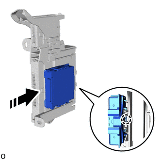

|
Install in this Direction |
Attach the claw to install the clearance warning ECU assembly as shown in the illustration.
82877
2.INSTALL ECU INTEGRATION BOX RH (for Manual Transaxle)
3.INSTALL INSTRUMENT PANEL JUNCTION BLOCK ASSEMBLY WITH MAIN BODY ECU (for Manual Transaxle)
89340A
4.INSTALL CLEARANCE WARNING ECU ASSEMBLY (except Manual Transaxle)
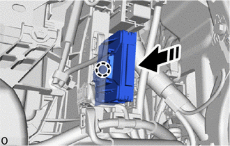
|
|
Install in this Direction |
Attach the claw to install the clearance warning ECU assembly as shown in the illustration.
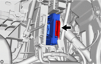
Connect the connector.
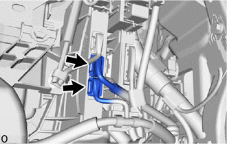
Connect the 2 connectors.
55433B
5.INSTALL LOWER NO. 2 INSTRUMENT PANEL FINISH PANEL
55550
6.INSTALL GLOVE COMPARTMENT DOOR ASSEMBLY
55607
7.INSTALL NO. 2 INSTRUMENT PANEL UNDER COVER SUB-ASSEMBLY
62111C
8.INSTALL COWL SIDE TRIM BOARD RH
67913B
9.INSTALL FRONT DOOR SCUFF PLATE RH
- HINT:
-
Use the same procedure described for the LH side.
-
Click hereVehicle Interior>INTERIOR PANELS / TRIM>ROOF HEADLINING>INSTALLATION
58810J
10.INSTALL CONSOLE BOX ASSEMBLY
11.CONNECT CABLE TO NEGATIVE AUXILIARY BATTERY TERMINAL (for Manual Transaxle)
Click hereGeneral>MAINTENANCE>M20A-FKS BATTERY>INSTALLATION
- NOTICE:
-
When disconnecting the cable, some systems need to be initialized after the cable is reconnected.
-
Click hereGeneral>INTRODUCTION>REPAIR INSTRUCTION>INITIALIZATION
12. PERFORM DIAGNOSTIC SYSTEM CHECK (for Manual Transaxle)
13.CHECK SRS WARNING LIGHT (for Manual Transaxle)
14.PERFORM CALIBRATION (w/ Parking Support Brake System)
for Gasoline Model: