EG62 MANUAL TRANSMISSION / TRANSAXLE MANUAL TRANSAXLE ASSEMBLY REMOVAL
CAUTION / NOTICE / HINT
The necessary procedures (adjustment, calibration, initialization, or registration) that must be performed after parts are removed, installed, or replaced during the manual transaxle assembly removal/installation are shown below.
| Replacement Part or Procedure | Necessary Procedure | Effect/Inoperative when not Performed | Link |
|---|---|---|---|
|
*1: When performing learning using the GTS. Click here( *2: w/ Gasoline Particulate Filter *3: When the starter assembly is replaced, "ST NO. 1 relay" must be also replaced. |
|||
| Battery terminal is disconnected/reconnected | Drive the vehicle until stop and start control is permitted (approximately 5 to 60 minutes) | Stop and start system | ( ) |
| Perform steering sensor zero point calibration | Lane control system | ()
|
|
| Parking support brake system (for Gasoline model)*1 | |||
| Pre-collision system | |||
| Memorize steering angle neutral point | Parking assist monitor system | ()
|
|
| Panoramic view monitor system (for Gasoline model) | ()
|
||
| Reset back door close position | Power back door system (for Gasoline model) | ()
|
|
| Power back door initialization | Power door lock control system | ()
|
|
| ECM | Perform Vehicle Identification Number (VIN) or frame number registration | DTC P063051 is output | ()
|
| ECU communication ID registration | Engine start function | See Service Bulletin for the registration method. | |
GPF Deposition Values*2 -
GPF deposition values save -
GPF deposition values write |
·
MIL comes on ·
Deterioration of fuel efficiency |
()
|
|
·
Air fuel ratio sensor (sensor 1) ·
Air fuel ratio sensor (sensor 2) ·
Air intake system parts ·
Gas leaks from exhaust system ·
Engine assembly |
Inspection after repair | ·
Poor idle, etc. ·
Engine start function, etc. |
()
|
| Front exhaust pipe assembly | GPF deposition value clear | ·
MIL comes on ·
Deterioration of fuel efficiency |
()
|
| Starter assembly*3 | Clear the number of starter operations | Stop and start system | ()
|
| Front bumper assembly (Including removal and installation) | ·
Ultrasonic sensor detection angle ·
Ultrasonic sensor detection angle registration |
Parking support brake system (for Gasoline model) | ()
|
| Front television camera view adjustment | Panoramic view monitor system (for Gasoline model) | ()
|
|
| Suspension, tires, etc. | ·
Ultrasonic sensor detection angle ·
Ultrasonic sensor detection angle registration |
Parking support brake system (for Gasoline model) | ()
|
| Television camera assembly optical axis (Back camera position setting) | Parking assist monitor system | ()
|
|
·
Parking assist ECU initialization ·
Adjust steering angle |
Panoramic view monitor system (for Gasoline model) | ()
|
|
| Front wheel alignment adjustment | ·
Perform reset memory ·
Perform acceleration sensor zero point calibration and store system information memorization. |
·
VSC is disabled or malfunctions ·
DTCs are output ·
Slip indicator light illuminates ·
ABS warning light illuminates |
()
|
- CAUTION:
- ·
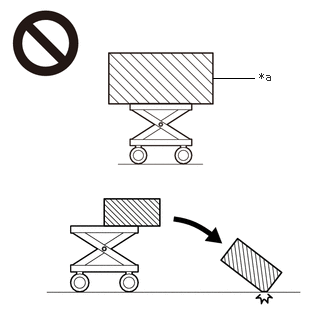 2.219,0.813 2.646,0.813 false 2.698,0.729 3.01,0.927 0.313,0.198 10 false *a
*a An Object Exceeding Weight Limit of Engine Lifter
The engine assembly with transaxle is very heavy. Be sure to follow the procedure described in the repair manual, or the engine lifter may suddenly drop or the engine assembly with transaxle may fall off the engine lifter.
·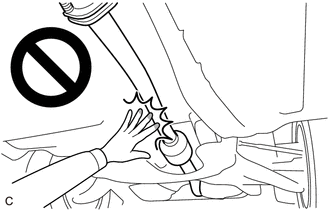
When the engine is hot, do not touch high-temperature areas such as the engine or exhaust pipe.
·Touching high-temperature areas such as the engine and exhaust pipe could result in burns.
- NOTICE:
-
When the manual transaxle assembly is removed, be sure to use a new clutch release cylinder with bearing assembly and new installation bolts. Removal of the manual transaxle assembly allows the compressed clutch release cylinder with bearing assembly to return to its original position. Dust from the moving section may damage the seal of the clutch release cylinder with bearing assembly, possibly causing clutch fluid leaks.
PROCEDURE

 1.REMOVE ENGINE ASSEMBLY WITH MANUAL TRANSAXLE ASSEMBLY
17141
2.REMOVE EXHAUST MANIFOLD
23825
3.REMOVE FUEL DELIVERY GUARD
4.INSTALL ENGINE HANGERS
45319
5.REMOVE STEERING GEAR HEAT INSULATOR (for LHD)
6.DISCONNECT WIRE HARNESS (for LHD)
7.DISCONNECT WIRE HARNESS (for RHD)
51100H
8.REMOVE FRONT FRAME ASSEMBLY
9.DISCONNECT WIRE HARNESS
Disconnect the wire harness from the manual transaxle assembly.
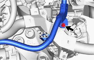
Remove the bolt and detach the clamp.
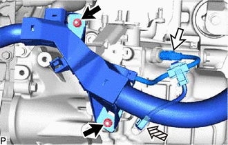

|
Nut |

|
Neutral Position Switch Connector |

|
Transmission Revolution Sensor Connector |
Remove the 2 nuts.
Disconnect the neutral position switch connector and transmission revolution sensor connector.
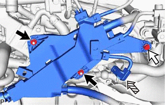
|
|
Nut |
|
|
Bolt |
|
|
Engine Coolant Temperature Sensor Connector |
Remove the 2 nuts and bolt.
Disconnect the engine coolant temperature sensor connector.
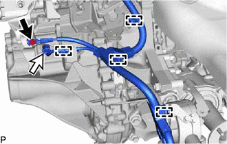
|
|
Bolt |
|
|
Back-up Light Switch Assembly Connector |
Remove the bolt and disconnect the back-up light switch assembly connector.
Detach the 4 clamps.
12372A
10.REMOVE TRANSVERSE ENGINE ENGINE MOUNTING INSULATOR
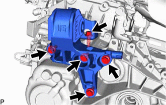
Remove the 5 bolts and transverse engine engine mounting insulator from the manual transaxle assembly.
12361
11.REMOVE FRONT ENGINE MOUNTING INSULATOR
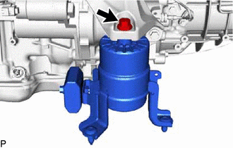
Remove the bolt and front engine mounting insulator from the transverse engine engine mounting bracket.
12311A
12.REMOVE TRANSVERSE ENGINE ENGINE MOUNTING BRACKET
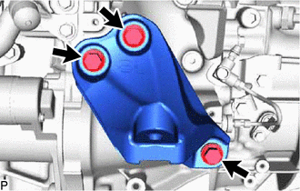
Remove the 3 bolts and transverse engine engine mounting bracket from the manual transaxle assembly.
12371A
13.REMOVE REAR ENGINE MOUNTING INSULATOR
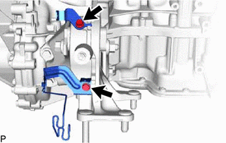
Remove the 2 bolts and 2 wire harness clamp brackets from the rear engine mounting insulator.
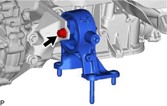
Remove the bolt, nut and rear engine mounting insulator from the rear engine mounting bracket sub-assembly.
12303
14.REMOVE REAR ENGINE MOUNTING BRACKET SUB-ASSEMBLY
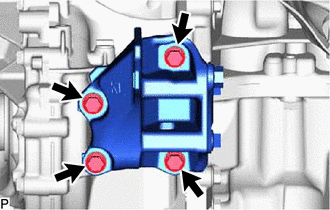
Remove the 4 bolts and rear engine mounting bracket sub-assembly from the manual transaxle assembly.
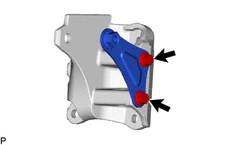
Remove the 2 bolts and rear No. 2 engine mounting bracket from the rear engine mounting bracket.
11363A
15.REMOVE FLYWHEEL HOUSING SIDE COVER
28100
16.REMOVE STARTER ASSEMBLY
for 1.2 kW Type:
Click hereEngine / Hybrid System>M20A-FKS (STARTING)>STARTER (for 1.2 kW Type)>REMOVAL
w/ Stop and Start System:
30300
17.REMOVE MANUAL TRANSAXLE ASSEMBLY
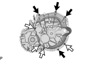
|
|
Bolt A |
|
|
Bolt B |
Remove the 8 bolts and manual transaxle assembly from the engine assembly.
- NOTICE:
-
To prevent damage to the 2 knock pins, do not pry between the manual transaxle assembly and engine assembly.
- HINT:
- ·
Bolt A: Remove from manual transaxle assembly side.
·Bolt B: Remove from engine assembly side.
31488F
18.REMOVE BLEEDER TO FLEXIBLE HOSE TUBE
Click hereDrivetrain>CLUTCH>CLUTCH UNIT>REMOVAL
31400
19.REMOVE CLUTCH RELEASE CYLINDER WITH BEARING ASSEMBLY
Click hereDrivetrain>CLUTCH>CLUTCH UNIT>REMOVAL
31482F
20.REMOVE CLUTCH RELEASE CYLINDER WITH BEARING ASSEMBLY TO BLEEDER TUBE
Click hereDrivetrain>CLUTCH>CLUTCH UNIT>REMOVAL
31407B
21.REMOVE CLUTCH RELEASE BLEEDER SUB-ASSEMBLY
Click hereDrivetrain>CLUTCH>CLUTCH UNIT>REMOVAL
31485
22.REMOVE CLUTCH FLEXIBLE HOSE BRACKET
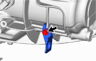
Remove the bolt and clutch flexible hose bracket from the manual transaxle assembly.
335A0
23.REMOVE CONTROL CABLE BRACKET ASSEMBLY
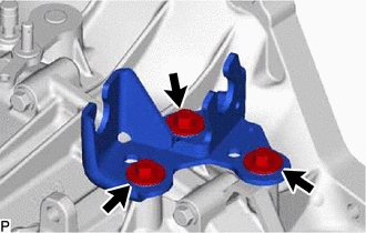
Remove the 3 bolts and control cable bracket assembly from the manual transaxle assembly.
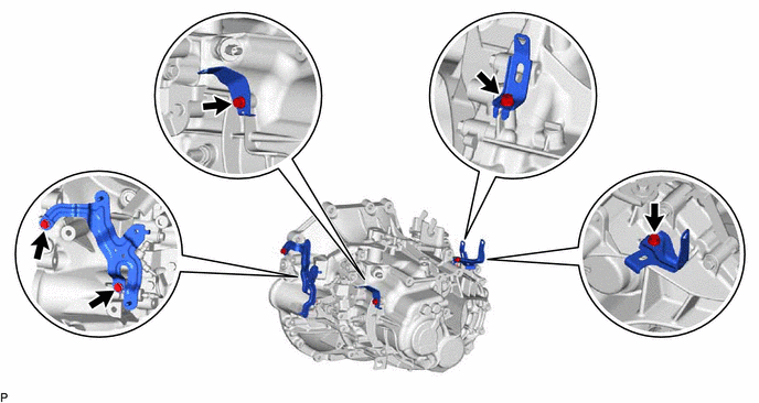
24.REMOVE WIRE HARNESS CLAMP BRACKET
Remove the 5 bolts and 4 wire harness clamp brackets.
35150D
25.REMOVE TRANSMISSION CASE PLUG ASSEMBLY
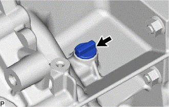
Remove the transmission case plug assembly from the manual transaxle assembly.