TELEMATICS ANTENNA DIVIDER INSTALLATION
CAUTION / NOTICE / HINT
- HINT:
- ·
Use the same procedure for RHD and LHD vehicles.
·The procedure listed below is for LHD vehicles.
PROCEDURE

 86681E
1.INSTALL ANTENNA DIVIDER
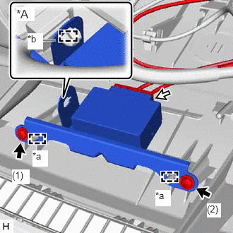
| *A | w/ Telematics Transceiver |
| *a | Guide |
| *b | Clamp |

|
Screw |

|
Connector |
Attach the guide to set the antenna divider.
Install the 2 screws in the order shown in the illustration.
Connect the connector.
w/ Telematics Transceiver:
Attach the clamp.
55950G
2.INSTALL DEFROSTER NOZZLE ASSEMBLY
3.INSTALL INSTRUMENT PANEL SAFETY PAD ASSEMBLY
4.CONNECT CABLE TO NEGATIVE AUXILIARY BATTERY TERMINAL
for A25A-FKS:
for M20A-FKS:
for A25A-FXS:
Click hereGeneral>MAINTENANCE>A25A-FXS AUXILIARY BATTERY>INSTALLATION
- NOTICE:
-
When disconnecting the cable, some systems need to be initialized after the cable is reconnected.
-
Click hereGeneral>INTRODUCTION>REPAIR INSTRUCTION>INITIALIZATION
65351A
5.INSTALL BATTERY HOLE COVER (for HV Model)
58416K
6.INSTALL REAR NO. 2 FLOOR BOARD (for HV Model)
58410B
7.INSTALL DECK BOARD ASSEMBLY (for HV Model)
8. PERFORM DIAGNOSTIC SYSTEM CHECK
w/o Occupant Classification System:
for Gasoline Model with Occupant Classification System:
for HV Model with Occupant Classification System:
9.CHECK SRS WARNING LIGHT
w/o Occupant Classification System:
for Gasoline Model with Occupant Classification System:
for HV Model with Occupant Classification System:
10.PERFORM SYSTEM INITIALIZATION AND CALIBRATION