STEERING GEAR / LINKAGE STEERING GEAR REMOVAL
CAUTION / NOTICE / HINT
The necessary procedures (adjustment, calibration, initialization, or registration) that must be performed after parts are removed and installed, or replaced during rack and pinion power steering gear assembly removal/installation are shown below.
| Replaced Part or Performed Procedure | Necessary Procedure | Effect/Inoperative Function when Necessary Procedure not Performed | Link |
|---|---|---|---|
|
*: When performing learning using the GTS. Click here( |
|||
| Auxiliary battery terminal is disconnected/reconnected | Perform steering sensor zero point calibration | Lane control system | ( ) |
| Parking support brake system (for HV model)* | |||
| Pre-collision system | |||
| Memorize steering angle neutral point | Parking assist monitor system | ()
|
|
| Panoramic view monitor system (for HV model) | ()
|
||
| Reset back door close position | Power back door system (for HV model) | ()
|
|
| Power back door initialization | Power door lock control system | ()
|
|
| ECM | for A25A-FXS(w/ Canister Pump Module):
Perform Vehicle Identification Number (VIN) registration |
DTC P063051 is output | ()
|
for A25A-FXS(w/o Canister Pump Module):
Perform Vehicle Identification Number (VIN) or frame number registration |
()
|
||
for A25B-FXS:
Perform Vehicle Identification Number (VIN) or frame number registration |
DTC P063051 is output | ()
|
|
for A25A-FXS:
·
Gas leak from exhaust system is repaired ·
Replacement of air fuel ratio sensor (sensor 2) |
Inspection after repair | ·
Poor idle, etc. ·
Engine start function, etc. |
w/ Canister Pump Module:
( )
w/o Canister Pump Module: ( )
|
for A25B-FXS:
·
Gas leak from exhaust system is repaired ·
Replacement of air fuel ratio sensor (sensor 2) |
Inspection after repair | ·
Poor idle, etc. ·
Engine start function, etc. |
()
|
| Inverter with converter assembly | Resolver learning | ·
DTCs are stored ·
Slight vibration at a vehicle speed of 5 km/h (3 mph) or less ·
Shock or vibration during acceleration |
()
|
| Hybrid vehicle transaxle assembly | ·
Resolver learning ·
Initialize resolver |
||
| Front wheel alignment adjustment | 1.
Clear zero point calibration data. 2.
Perform yaw rate and acceleration sensor zero point calibration. |
·
DTCs are stored ·
ABS warning light illuminates ·
Brake warning light / yellow (minor malfunction) illuminates ·
Slip indicator light illuminates ·
VSC disabled or malfunctions |
()
|
| Front bumper assembly (Including removal and installation) | ·
Ultrasonic sensor detection angle ·
Ultrasonic sensor detection angle registration |
Parking support brake system (for HV model) | ()
|
| Front television camera view adjustment | Panoramic view monitor system (for HV model) | ()
|
|
| Suspension, tires, etc.
(The vehicle height changes because of suspension or tire replacement) |
·
Ultrasonic sensor detection angle ·
Ultrasonic sensor detection angle registration |
Parking support brake system (for HV model) | ()
|
| Television camera assembly optical axis (Back camera position setting) | Parking assist monitor system | ()
|
|
·
Parking assist ECU initialization ·
Adjust steering angle |
Panoramic view monitor system (for HV model) | ()
|
|
| Replacement of the headlight ECU sub-assembly LH | ·
Synchronize the vehicle information ·
Perform headlight ECU sub-assembly LH initialization |
Lighting system (EXT) | ()
|
| Rack and pinion power steering gear assembly | ·
Perform torque sensor zero point calibration ·
Assist map writing |
·
DTCs are output ·
EPS warning light illuminates |
()
|
| Replaced Part or Performed Procedure | Necessary Procedure | Effect/Inoperative Function when Necessary Procedure not Performed | Link |
|---|---|---|---|
|
*1: When performing learning using the GTS. Click here( *2: w/ Gasoline Particulate Filter |
|||
| Disconnect cable from negative (-) auxiliary battery terminal | Drive the vehicle until stop and start control is permitted (approximately 5 to 60 minutes) | Stop and start system | for A25A-FKS:
( )
for M20A-FKS: ( )
|
| Perform steering sensor zero point calibration | Lane control system | ()
|
|
| Parking support brake system (for Gasoline model)* | |||
| Pre-collision system | |||
| Memorize steering angle neutral point | Parking assist monitor system | ()
|
|
| Panoramic view monitor system (for Gasoline model) | ()
|
||
| Reset back door close position | Power back door system (for Gasoline model) | ()
|
|
| Power back door initialization | Power door lock control system | ()
|
|
| Replacement of ECM | Perform Vehicle Identification Number (VIN) or frame number registration | DTC P063051 is output | A25A-FKS (w/ Canister Pump Module):
( )
A25A-FKS (w/o Canister Pump Module): ( )
M20A-FKS: ( )
|
| ECU communication ID registration | Engine start function | See Service Bulletin for the registration method. | |
for M20A-FKS:
GPF Deposition Values*2 -
GPF deposition values save -
GPF deposition values write |
·
MIL comes on ·
Deterioration of fuel efficiency |
()
|
|
·
Replacement of engine assembly ·
Gas leak from exhaust system is repaired |
Inspection after repair | ·
Poor idle, etc. ·
Engine start function, etc. |
A25A-FKS (w/ Canister Pump Module):
( )
A25A-FKS (w/o Canister Pump Module): ( )
M20A-FKS: ( )
|
for M20A-FKS:
Front exhaust pipe assembly |
GPF deposition value clear | ·
MIL comes on ·
Deterioration of fuel efficiency |
()
|
| Replacement of automatic transaxle assembly | for UB80E:
·
Reset memory ·
Input transaxle compensation code into ECM ·
Perform road test to allow ECM to learn |
·
Large shift shock ·
Deterioration of fuel efficiency |
for Initialization:
( )
for Registration: ( )
|
for UB80F:
·
Reset memory ·
Input transaxle compensation code into ECM ·
Perform road test to allow ECM to learn |
·
Large shift shock ·
Deterioration of fuel efficiency |
for Initialization:
( )
for Registration: ( )
|
|
| Automatic transaxle fluid | ATF thermal degradation estimate reset | The value of the Data List item "ATF Thermal Degradation Estimate" is not estimated correctly | for UB80E:
( )
for UB80F: ( )
|
| Continuously variable transaxle assembly | Air bleed oil pump with motor assembly (w/ Stop and Start System) | Stop and start system | ()
|
for K120:
·
Input transaxle compensation code into TCM ·
Perform reset memory ·
Deceleration sensor zero point calibration ·
CVT oil pressure calibration ·
Perform road test to allow TCM to learn |
·
Large shift shock ·
Deterioration of fuel efficiency |
for Initialization:
( )
for Registration: ( )
|
|
for K120F:
·
Input transaxle compensation code into TCM ·
Perform reset memory ·
Deceleration sensor zero point calibration ·
CVT oil pressure calibration ·
Perform road test to allow TCM to learn |
·
Large shift shock ·
Deterioration of fuel efficiency |
for Initialization:
( )
for Registration: ( )
|
|
| CVT fluid | ATF thermal degradation estimate reset | The value of the Data List item "ATF Thermal Degradation Estimate" is not estimated correctly | for K120:
( )
for K120F: ( )
|
| Air bleed oil pump with motor assembly (w/ Stop and Start System) | Stop and start system | ()
|
|
| Suspension, tires, etc.
(The vehicle height changes because of suspension or tire replacement) |
·
Ultrasonic sensor detection angle ·
Ultrasonic sensor detection angle registration |
Parking Support Brake System (for Gasoline model) | ()
|
| Television camera assembly optical axis (Back camera position setting) | Parking Assist Monitor System | ()
|
|
·
Parking assist ECU initialization ·
Adjust steering angle |
Panoramic View Monitor System (for Gasoline model) | ()
|
|
| Front wheel alignment adjustment | ·
Perform reset memory ·
Perform acceleration sensor zero point calibration and store system information memorization. |
·
VSC is disabled or malfunctions ·
DTCs are output ·
Slip indicator light illuminates ·
ABS warning light illuminates |
()
|
| Front bumper assembly (Including removal and installation) | ·
Ultrasonic sensor detection angle ·
Ultrasonic sensor detection angle registration |
Parking support brake system (for Gasoline model) | ()
|
| Front television camera view adjustment | Panoramic view monitor system (for Gasoline model) | ()
|
|
| Replacement of the headlight ECU sub-assembly LH | ·
Synchronize the vehicle information ·
Perform headlight ECU sub-assembly LH initialization |
Lighting system (EXT) | ()
|
| Rack and pinion power steering gear assembly | ·
Perform torque sensor zero point calibration ·
Assist map writing |
·
DTCs are output ·
EPS warning light illuminates |
()
|
- NOTICE:
-
After the ignition switch is turned off, the navigation system requires approximately a minute to record various types of memory and settings. As a result, after turning the ignition switch off, wait a minute or more before disconnecting the cable from the negative (-) auxiliary battery terminal.
PROCEDURE

 1. PRECAUTION
- NOTICE:
-
After turning the ignition switch off, waiting time may be required before disconnecting the cable from the negative (-) battery terminal. Therefore, make sure to read the disconnecting the cable from the negative (-) battery terminal notice before proceeding with work.
When handling the rack and pinion power steering gear assembly:
Do not subject the rack and pinion power steering gear assembly (especially the motor and torque sensor) to any impact. Replace the rack and pinion power steering gear assembly with a new one if subjected to a strong impact.
Do not pull the wire harness when moving the rack and pinion power steering gear assembly.
When the rack and pinion power steering gear assembly has been replaced, perform torque sensor zero point calibration.
Click hereSteering>POWER ASSIST SYSTEMS>POWER STEERING SYSTEM>CALIBRATION
When disconnecting or reconnecting the connectors:
Before disconnecting connectors related to the power steering system, turn the ignition switch ON, center the steering wheel, turn the ignition switch off, and then disconnect the connectors.
Before reconnecting connectors related to the power steering system, ensure that the ignition switch is off. Then center the steering wheel and turn the ignition switch on.
- NOTICE:
-
Do not turn the ignition switch ON when the steering wheel is not centered.
If the above operations are not carried out properly, the steering center point (zero point) will deviate, which may lead to a difference in steering effort between turning right and left.
- HINT:
-
If there is a difference in steering effort between turning right and left, perform torque sensor zero point calibration.
-
Click hereSteering>POWER ASSIST SYSTEMS>POWER STEERING SYSTEM>CALIBRATION
2. ALIGN FRONT WHEELS FACING STRAIGHT AHEAD
3. SECURE STEERING WHEEL
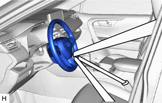
Secure the steering wheel with the seat belt in order to prevent rotation.
- HINT:
-
This operation is useful to prevent damage to the spiral cable.
4.REMOVE FRONT WHEELS
45220
5.SEPARATE STEERING INTERMEDIATE SHAFT ASSEMBLY
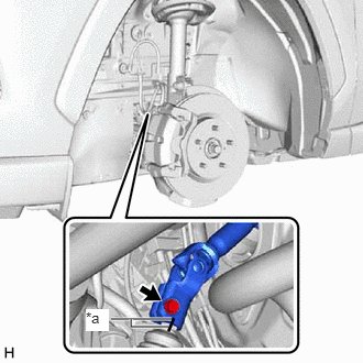
| *a | Matchmark |
Remove the bolt and slide the steering intermediate shaft assembly.
- NOTICE:
-
Do not separate the steering intermediate shaft assembly from the rack and pinion power steering gear assembly.
Put matchmarks on the rack and pinion power steering gear assembly and steering intermediate shaft assembly.
Separate the steering intermediate shaft assembly from the rack and pinion power steering gear assembly.
45470
6.DISCONNECT TIE ROD ASSEMBLY LH
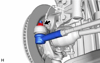
Remove the cotter pin and nut.
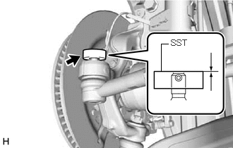
Install SST to the tie rod assembly LH as shown in the illustration.
- SST
- 09960-20010 (09961-02060)
- NOTICE:
-
Make sure that the upper ends of the tie rod assembly LH and SST are aligned.
Using SST, separate the tie rod assembly LH from the steering knuckle LH as shown in the illustration.
- SST
- 09960-20010 (09961-02010)
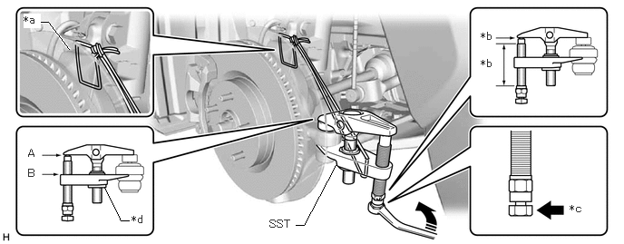
| *a | String | *b | Molybdenum Grease Application Area |
| *c | Place wrench here | *d | Center Nut |

|
Turn | - | - |
- CAUTION:
-
Apply molybdenum grease to the threads and end of the SST bolt.
- NOTICE:
- ·
Be sure to tighten the string firmly to secure SST to the steering knuckle LH to prevent SST from falling off.
·Install SST with the center nut so that (A) and (B) shown in the illustration are parallel. Otherwise, the ball joint dust cover may be damaged.
·Be sure to place the wrench on the part shown in the illustration.
·Do not damage the front disc brake dust cover.
·Do not damage the ball joint dust cover.
·Do not damage the steering knuckle LH.
45460
7.DISCONNECT TIE ROD ASSEMBLY RH
- HINT:
-
Perform the same procedure as for the LH side.
8.REMOVE ENGINE ASSEMBLY WITH TRANSAXLE
for A25A-FKS: Click hereEngine / Hybrid System>A25A-FKS (ENGINE MECHANICAL)>ENGINE ASSEMBLY>REMOVAL
for M20A-FKS: Click hereEngine / Hybrid System>M20A-FKS (ENGINE MECHANICAL)>ENGINE ASSEMBLY>REMOVAL
for A25A-FXS: Click hereEngine / Hybrid System>A25A-FXS (ENGINE MECHANICAL)>ENGINE ASSEMBLY>REMOVAL
for A25B-FXS: Click hereEngine / Hybrid System>A25B-FXS (ENGINE MECHANICAL)>ENGINE ASSEMBLY>REMOVAL
45319
9.REMOVE STEERING GEAR HEAT INSULATOR (for LHD)
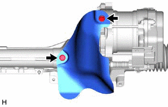
Remove the 2 bolts and steering gear heat insulator from the rack and pinion power steering gear assembly.
10.DISCONNECT WIRE HARNESS (for LHD)
Disconnect the wire harness connector from the rack and pinion power steering gear assembly.
- HINT:
-
Release the lock before rotating the lock lever.
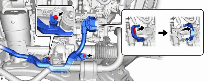
Remove the 2 bolts and separate the wire harness from the rack and pinion power steering gear assembly.
11.DISCONNECT WIRE HARNESS (for RHD)
Disconnect the wire harness connector from the rack and pinion power steering gear assembly.
- HINT:
-
Release the lock before rotating the lock lever.
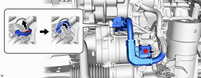
Remove the bolt and separate the wire harness from the rack and pinion power steering gear assembly.
23825
12.REMOVE FUEL DELIVERY GUARD
for A25A-FKS: Click hereEngine / Hybrid System>A25A-FKS (ENGINE MECHANICAL)>ENGINE ASSEMBLY>REMOVAL
for M20A-FKS: Click hereEngine / Hybrid System>M20A-FKS (ENGINE MECHANICAL)>ENGINE ASSEMBLY>REMOVAL
for A25A-FXS: Click hereEngine / Hybrid System>A25A-FXS (ENGINE MECHANICAL)>ENGINE ASSEMBLY>REMOVAL
for A25B-FXS: Click hereEngine / Hybrid System>A25B-FXS (ENGINE MECHANICAL)>ENGINE ASSEMBLY>REMOVAL
13.INSTALL ENGINE HANGER
for A25A-FKS: Click hereEngine / Hybrid System>A25A-FKS (ENGINE MECHANICAL)>ENGINE ASSEMBLY>REMOVAL
for M20A-FKS: Click hereEngine / Hybrid System>M20A-FKS (ENGINE MECHANICAL)>ENGINE ASSEMBLY>REMOVAL
for A25A-FXS: Click hereEngine / Hybrid System>A25A-FXS (ENGINE MECHANICAL)>ENGINE ASSEMBLY>REMOVAL
for A25B-FXS: Click hereEngine / Hybrid System>A25B-FXS (ENGINE MECHANICAL)>ENGINE ASSEMBLY>REMOVAL
14.REMOVE FRONT FRAME ASSEMBLY
for HV model: Click hereSuspension>FRONT SUSPENSION>FRONT SUSPENSION MEMBER (for HV Model)>REMOVAL
for Gasoline model(2WD): Click hereSuspension>FRONT SUSPENSION>FRONT SUSPENSION MEMBER (for Gasoline Model)>REMOVAL
for Gasoline model(4WD/AWD): Click hereSuspension>FRONT SUSPENSION>FRONT SUSPENSION MEMBER (for Gasoline Model)>REMOVAL
15.REMOVE FRONT STABILIZER BAR WITH BRACKET
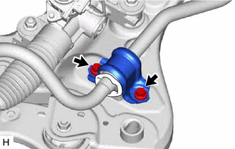
Remove the 2 bolts and separate the front No. 1 stabilizer bracket LH from the front frame assembly.
Remove the 2 bolts and separate the front No. 1 stabilizer bracket RH from the front frame assembly.
- HINT:
-
Perform the same procedure as for the LH side.
Remove the front stabilizer bar with 2 front stabilizer links, front No. 1 stabilizer bracket LH, front No. 1 stabilizer bracket RH and 2 front No. 1 stabilizer bar bushings from the front frame assembly.
44250
16.REMOVE RACK AND PINION POWER STEERING GEAR ASSEMBLY
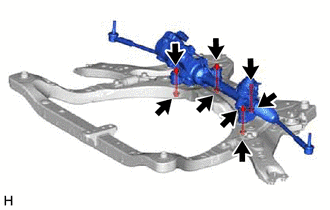
Remove the 4 bolts, 4 nuts and rack and pinion power steering gear assembly from the front frame assembly.
- NOTICE:
-
Because the nut has its own stopper, do not turn the nut. Loosen the bolt with the nut secured.
44250
17.SECURE RACK AND PINION POWER STEERING GEAR ASSEMBLY
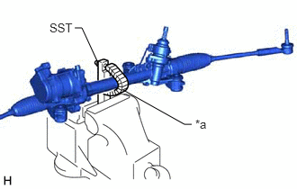
| *a | Protective Tape |
Using SST, secure the rack and pinion power steering gear assembly in a vise.
- SST
- 09612-00012
- HINT:
-
Wrap SST with protective tape before use.
45470
18.REMOVE TIE ROD ASSEMBLY LH
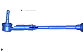
| *a | Matchmark |
Put matchmarks on the tie rod assembly LH and rack and pinion power steering gear assembly.
Remove the tie rod assembly LH and lock nut.
45460
19.REMOVE TIE ROD ASSEMBLY RH
- HINT:
-
Perform the same procedure as for the LH side.
45319
20.REMOVE STEERING GEAR HEAT INSULATOR (for RHD)
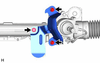
Remove the 3 bolts and steering gear heat insulator from the rack and pinion power steering gear assembly.