A25A-FXS FUEL FUEL FILTER(w/o Canister Pump Module) REPLACEMENT
CAUTION / NOTICE / HINT
The necessary procedures (adjustment, calibration, initialization or registration) that must be performed after parts are removed and installed, or replaced fuel sub-tank sub-assembly removal/installation are shown below.
| Replaced Part or Performed Procedure | Necessary Procedure | Effect/Inoperative Function when Necessary Procedure not Performed | Link |
|---|---|---|---|
|
*: When performing learning using the GTS. Click here( |
|||
| Auxiliary battery terminal is disconnected/reconnected | Perform steering sensor zero point calibration | Lane control system | ( ) |
| Parking support brake system* | |||
| Pre-collision system | |||
| Memorize steering angle neutral point | Parking assist monitor system | ()
|
|
| Panoramic view monitor system | ()
|
||
| Reset back door close position | Power back door system | ()
|
|
| Power back door initialization | Power door lock control system | ()
|
|
- CAUTION:
- ·
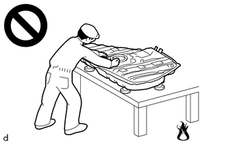
Never perform work on fuel system components near any possible ignition sources.
·Vaporized fuel could ignite, resulting in a serious accident.
- ·
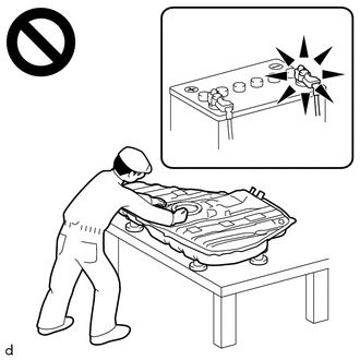
Do not perform work on fuel system components without first disconnecting the cable from the negative (-) auxiliary battery terminal.
·Sparks could cause vaporized fuel to ignite, resulting in a serious accident.
- NOTICE:
-
Do not disconnect the tube shown in the illustration when disassembling the fuel suction tube with pump and gauge assembly. Doing so will cause reassembly of the fuel suction tube with pump and gauge assembly to be impossible as the tube is pressed into the fuel suction plate sub-assembly.
-
Click hereEngine / Hybrid System>A25A-FXS (FUEL)>FUEL SYSTEM>PRECAUTION
PROCEDURE

 58410B
1.REMOVE DECK BOARD ASSEMBLY
58416K
2.REMOVE REAR NO. 2 FLOOR BOARD
65351A
3.REMOVE BATTERY HOLE COVER
4.DISCONNECT CABLE FROM NEGATIVE AUXILIARY BATTERY TERMINAL
- NOTICE:
-
When disconnecting the cable, some systems need to be initialized after the cable is reconnected.
-
Click hereGeneral>INTRODUCTION>REPAIR INSTRUCTION>INITIALIZATION
77020A
5.REMOVE FUEL SUCTION WITH PUMP AND GAUGE TUBE ASSEMBLY
83320
6.REMOVE FUEL SENDER GAUGE ASSEMBLY
77103
7.REMOVE FUEL SUB-TANK SUB-ASSEMBLY
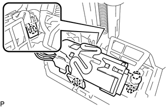
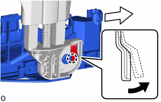
Detach the 4 claws and disconnect the sub-assembly support from the fuel sub-tank sub-assembly.
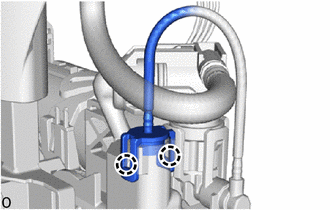
Detach the 2 claw and disconnect the No. 1 fuel tube from the fuel sub-tank sub-assembly.

|
Pull |

|
Slide |
Detach the claw and slide the fuel sub-tank sub-assembly and disconnect it from the fuel suction plate sub-assembly.
77103
8.INSTALL FUEL SUB-TANK SUB-ASSEMBLY
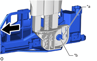
| *a | Installation Hole |
| *b | Protrusion |
|
|
Slide |
Align the protrusion of the fuel sub-tank sub-assembly with the installation hole of the fuel suction plate sub-assembly and slide the fuel sub-tank sub-assembly to install the fuel suction plate sub-assembly.
Attach the 2 claw and connect the No. 1 fuel tube to the fuel sub-tank sub-assembly.
Attach the 4 claws and connect the sub-assembly support to the fuel sub-tank sub-assembly.
83320
9.INSTALL FUEL SENDER GAUGE ASSEMBLY
77020A
10.INSTALL FUEL SUCTION WITH PUMP AND GAUGE TUBE ASSEMBLY
11.CONNECT CABLE TO NEGATIVE AUXILIARY BATTERY TERMINAL
- NOTICE:
-
When disconnecting the cable, some systems need to be initialized after the cable is reconnected.
-
Click hereGeneral>INTRODUCTION>REPAIR INSTRUCTION>INITIALIZATION
65351A
12.INSTALL BATTERY HOLE COVER
58416K
13.INSTALL REAR NO. 2 FLOOR BOARD
58410B
14.INSTALL DECK BOARD ASSEMBLY