 |
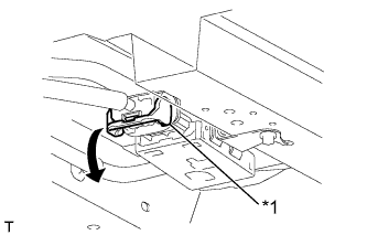
Turn the lock lever and disconnect the connector of the fuel pump ECU.
| *1 | Lock Lever |
ENGINE ASSEMBLY > REMOVAL |
| 1. PRECAUTION |
| 2. DISCHARGE FUEL SYSTEM PRESSURE |
Disconnect the cable from the negative (-) battery terminal.
|
Turn the lock lever and disconnect the connector of the fuel pump ECU.
| *1 | Lock Lever |
Connect the cable to the negative (-) battery terminal.
Start the engine. After the engine has stopped on its own, turn the ignition switch off.
Crank the engine again, then check that the engine does not start.
Loosen the fuel tank cap, then discharge the pressure in the fuel tank completely.
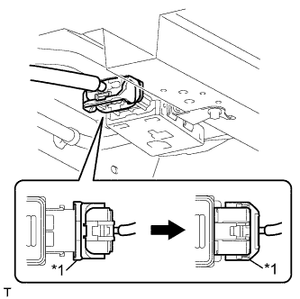 |
Connect the connector of the fuel pump ECU.
Turn the lock lever and secure the connector with the lock lever.
| *1 | Lock Lever |
| 3. DISCONNECT CABLE FROM NEGATIVE BATTERY TERMINAL |
| 4. REMOVE FRONT WIPER MOTOR AND LINK ASSEMBLY |
Remove the front wiper motor and link (Click here).
| 5. REMOVE NO. 1 ENGINE UNDER COVER |
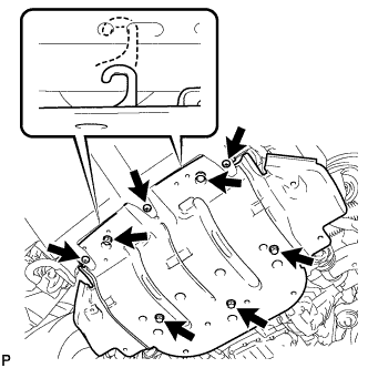 |
Remove the 3 screws and 5 bolts.
Unhook the engine under cover from the vehicle body as shown in the illustration.
| 6. DRAIN ENGINE OIL |
Remove the oil filler cap.
Remove the oil pan drain plug and gasket, and drain the engine oil into a container.
Install a new gasket and the oil pan drain plug.
| 7. DRAIN ENGINE COOLANT |
Loosen the radiator drain cock plug.
Remove the radiator cap. Then drain the coolant from the radiator.
Loosen the 2 cylinder block drain cock plugs. Then drain the coolant from the engine.
Tighten the 2 cylinder block drain cock plugs.
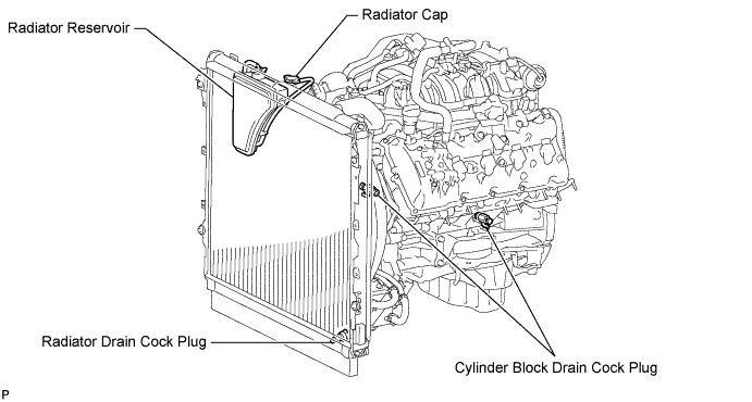
Tighten the radiator drain cock plug by hand.
| 8. REMOVE HOOD SUB-ASSEMBLY |
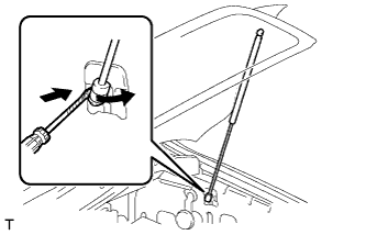 |
Using a screwdriver, release the 2 clips and remove the 2 hood supports assembly.
Remove the 4 bolts and hood.
| 9. REMOVE V-BANK COVER SUB-ASSEMBLY |
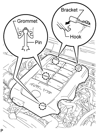 |
Raise the front of the V-bank cover to detach the 2 pins. Then remove the 2 V-bank cover hooks from the bracket, and remove the V-bank cover.
| 10. REMOVE AIR CLEANER HOSE ASSEMBLY |
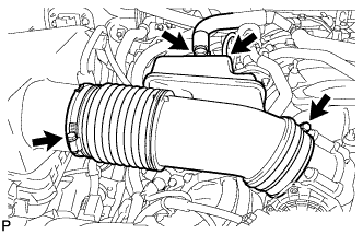 |
Disconnect the vacuum sensing hose and ventilation hose.
Loosen the 2 clamps.
Remove the air cleaner hose.
| 11. REMOVE AIR CLEANER ASSEMBLY |
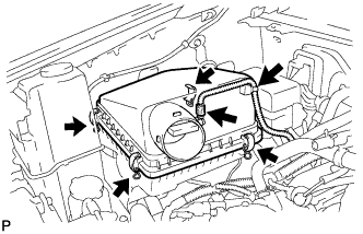 |
Remove the air cleaner cap.
Disconnect the MAF meter connector.
Using a clip remover, detach the wire harness clamp.
Unfasten the 4 hook clamps and then remove the air cleaner cap.
Remove the air cleaner element.
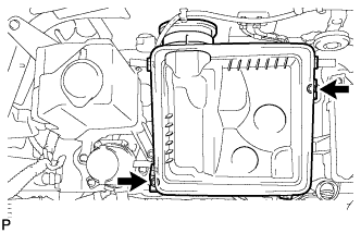 |
Remove the 2 bolts and air cleaner case.
| 12. REMOVE COWL TOP OUTER PANEL SUB-ASSEMBLY |
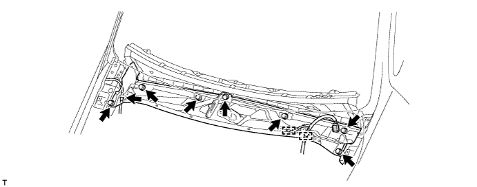
Disconnect the washer hose and 2 wire harness clamps.
Remove the 7 bolts and outer panel.
| 13. REMOVE FRONT FENDER APRON SEAL RH |
Remove the 6 clips and fender apron seal.
| 14. REMOVE FRONT FENDER APRON SEAL REAR RH |
Remove the 5 clips and fender apron seal.
| 15. REMOVE FRONT FENDER APRON SEAL LH |
Remove the 6 clips and fender apron seal.
| 16. REMOVE FRONT FENDER APRON SEAL REAR LH |
Remove the 5 clips and fender apron seal.
| 17. REMOVE FRONT BUMPER COVER |
Remove the front bumper cover (Click here).
| 18. REMOVE INLET RADIATOR HOSE |
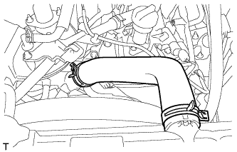 |
Remove the radiator hose.
| 19. DISCONNECT OUTLET RADIATOR HOSE |
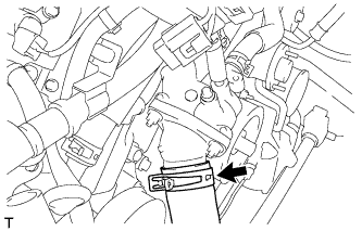 |
Disconnect the radiator hose.
| 20. REMOVE RADIATOR SIDE DEFLECTOR RH |
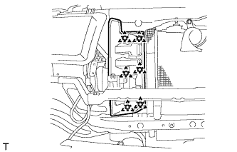 |
Using a clip remover, remove the 6 clips and side deflector.
| 21. REMOVE RADIATOR SIDE DEFLECTOR LH |
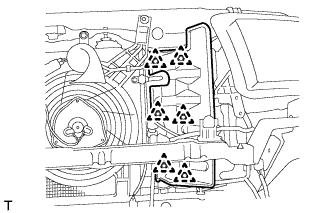 |
Using a clip remover, remove the 6 clips and side deflector.
Disconnect the wire harness clamp.
| 22. REMOVE FAN AND GENERATOR V BELT |
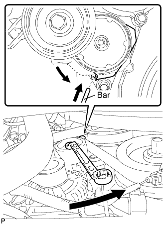 |
While turning the belt tensioner counterclockwise, align the service hole for the belt tensioner and the belt tensioner fixing position, and then insert a bar of φ 5 mm (0.197 in.) into the service hole to fix the belt tensioner in place.
Remove the V belt.
| 23. REMOVE FAN SHROUD |
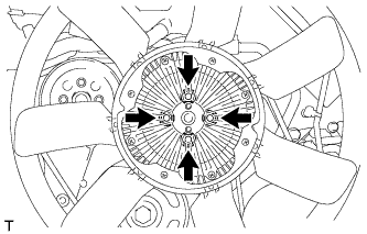 |
Loosen the 4 nuts holding the fluid coupling fan.
Remove the fan generator V-belt (Click here).
Disconnect the reservoir hose from the upper radiator tank.
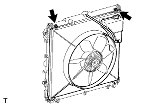 |
Remove the 2 bolts holding the fan shroud.
Remove the 4 nuts of the fluid coupling fan, and then remove the shroud together with the fluid coupling fan.
Remove the fan pulley from the fan bracket.
| 24. REMOVE NO. 1 RADIATOR TO SUPPORT SEAL (for LH Side) |
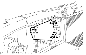 |
Remove the 3 clips and remove the No. 1 radiator to support seal.
| 25. REMOVE NO. 1 RADIATOR TO SUPPORT SEAL (for RH Side) |
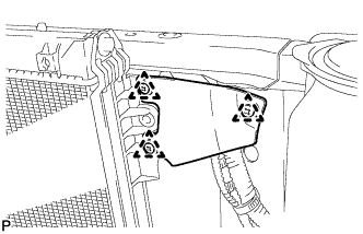 |
Remove the 3 clips and remove the No. 1 radiator to support seal.
| 26. REMOVE RADIATOR ASSEMBLY |
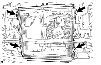 |
Remove the 4 bolts and radiator.
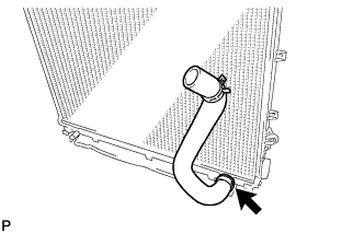 |
Remove the radiator hose from the radiator.
Remove the drain cock plug.
Remove the O-ring.
| 27. DISCONNECT NO. 12 WATER BY-PASS HOSE |
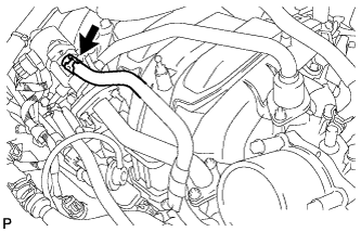 |
Disconnect the No. 12 water by-pass hose.
| 28. DISCONNECT NO. 13 WATER BY-PASS HOSE |
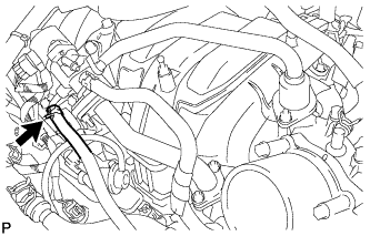 |
Disconnect the No. 13 water by-pass hose.
| 29. REMOVE EGR VALVE ASSEMBLY |
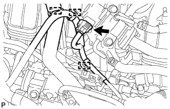 |
Disconnect the 3 clamps and connector.
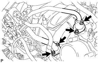 |
Remove the 4 nuts.
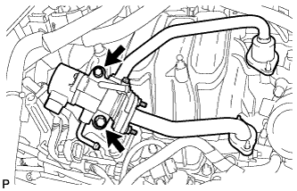 |
Remove the 2 bolts and EGR valve.
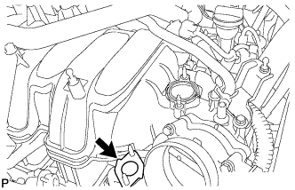 |
Remove the gasket from the No. 2 EGR pipe.
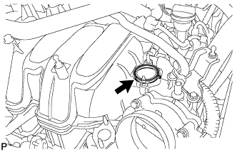 |
Remove the gasket from the intake manifold.
| 30. REMOVE EGR VALVE BRACKET |
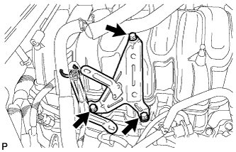 |
Remove the 3 bolts and EGR valve bracket.
| 31. REMOVE VENTILATION HOSE ASSEMBLY |
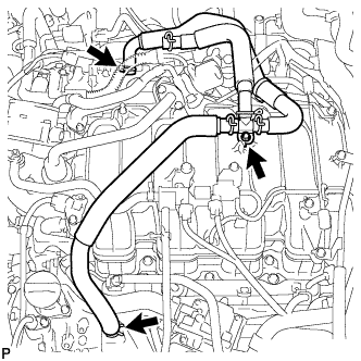 |
Disconnect the ventilation hose from the ventilation pipe of the cylinder head cover LH and RH.
Remove the bolt and ventilation hose.
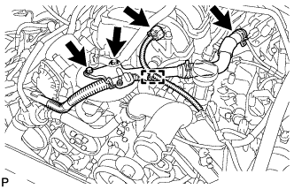
| 32. REMOVE AIR TUBE SUB-ASSEMBLY LH |
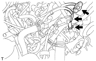 |
Disconnect the 2 connectors.
Disconnect the water by-pass hose.
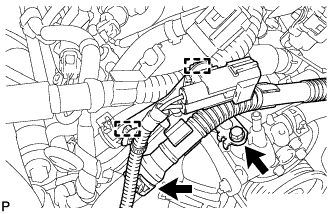 |
Disconnect the 2 wire harness clamps and air hose.
Remove the bolt and disconnect the air tube LH from the water inlet housing.
 |
Disconnect the vacuum sensor connector and clamp.
Remove the 2 bolts and disconnect the air hose from the air switching valve LH.
Remove the air tube LH.
| 33. REMOVE INTAKE MANIFOLD |
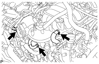 |
Disconnect the No. 4 water by-pass hose.
Disconnect the throttle body connector.
Disconnect the No. 1 ventilation hose.
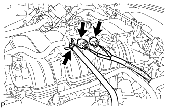 |
Disconnect the purge VSV connector.
Disconnect the purge line hose from the purge VSV.
Disconnect the vacuum switching valve connector (for ACIS).
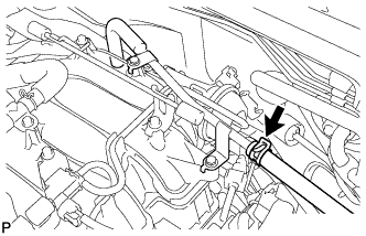 |
Disconnect the vacuum hose.
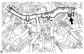 |
Remove the bolt and disconnect the wire harness from the wire harness bracket.
Detach the 3 wire harness clamps from the 3 wire harness brackets.
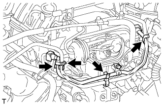 |
Detach the 4 clamps from the fuel tube.
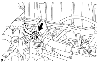 |
Disconnect the fuel tube from the fuel delivery pipe RH (Click here).
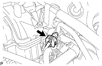 |
Disconnect the fuel tube from the fuel delivery pipe LH (Click here).
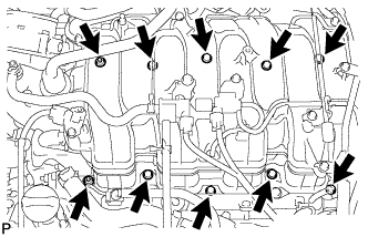 |
Remove the 2 nuts, 8 bolts, intake manifold and 2 gaskets.
| 34. DISCONNECT NO. 1 FUEL PIPE SUB-ASSEMBLY |
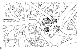 |
Remove the fuel pipe clamp.
Disconnect the No. 1 fuel pipe (Click here).
| 35. DISCONNECT NO. 2 FUEL TUBE SUB-ASSEMBLY |
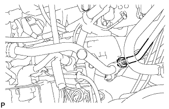 |
Disconnect the No. 2 fuel tube (Click here).
| 36. DISCONNECT WIRE HARNESS AND HOSE |
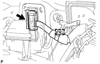 |
Disconnect the clamp and ECM connector.
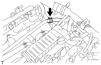 |
Disconnect the No. 4 water by-pass hose.
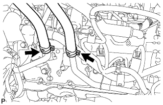 |
Disconnect the 2 heater hoses.
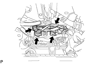 |
Disconnect the 4 connectors from the connector holder block.
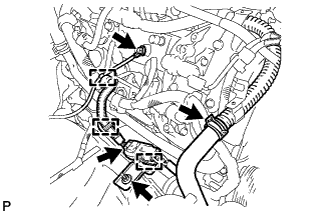 |
Remove the bolt and disconnect the clamp and ground wire.
Disconnect the air pump connector and 2 clamps.
Remove the nut and connector bracket.
Disconnect the air injection system hose.
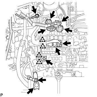 |
Remove the nut and disconnect the wire from the positive (+) battery cable.
Disconnect the cable from the positive (+) battery terminal.
Remove the bolt and disconnect the ground wire.
Disconnect the 4 air injection control driver connectors.
Remove the nut and disconnect the wire and 2 clips from the engine room junction block.
Disconnect the 2 connectors and 2 clips from the engine room junction block.
| 37. DISCONNECT COOLER COMPRESSOR ASSEMBLY |
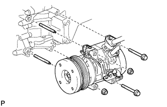 |
Remove the 2 bolts, 2 nuts and 2 stud bolts, and disconnect the cooler compressor.
| 38. DISCONNECT VANE PUMP ASSEMBLY |
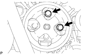 |
Remove the 2 bolts and disconnect the vane pump.
| 39. REMOVE GENERATOR ASSEMBLY |
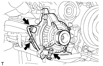 |
Remove the terminal cap.
Disconnect the generator connector.
Remove the nut and disconnect the generator wire.
Remove the bolt and disconnect the wire harness bracket from the generator.
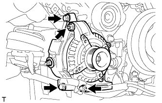 |
Remove the 3 bolts, nut and generator.
| 40. REMOVE PROPELLER SHAFT ASSEMBLY |
for 2WD:
Refer to the following procedures (Click here).
for 4WD:
Refer to the following procedures (Click here).
| 41. REMOVE FRONT PROPELLER SHAFT ASSEMBLY (for 4WD) |
Remove the front propeller shaft (Click here).
| 42. REMOVE EXHAUST PIPE ASSEMBLY |
Remove the exhaust pipe (Click here).
| 43. DISCONNECT NO. 1 WATER BY-PASS PIPE |
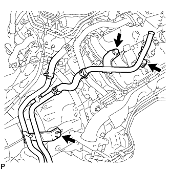 |
Remove the 3 bolts and disconnect the No. 1 water by-pass pipe.
| 44. REMOVE ENGINE OIL LEVEL DIPSTICK GUIDE |
Remove the dipstick.
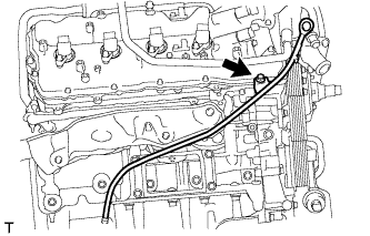 |
Remove the bolt and dipstick guide.
Remove the O-ring from dipstick guide.
| 45. REMOVE NO. 1 EGR PIPE SUB-ASSEMBLY |
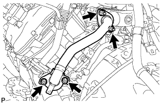 |
Remove the 4 nuts and EGR pipe.
Remove the 2 gaskets.
| 46. REMOVE NO. 2 EXHAUST MANIFOLD HEAT INSULATOR |
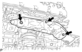 |
Remove the 3 bolts and heat insulator.
| 47. REMOVE EXHAUST MANIFOLD SUB-ASSEMBLY LH |
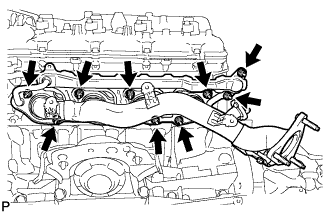 |
Remove the 9 nuts, exhaust manifold and 2 gaskets.
| 48. REMOVE NO. 1 EXHAUST MANIFOLD HEAT INSULATOR |
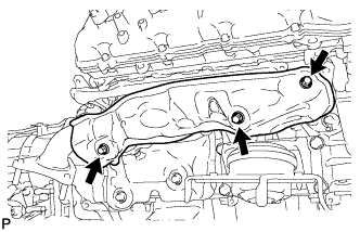 |
Remove the 3 bolts and heat insulator.
| 49. REMOVE EXHAUST MANIFOLD SUB-ASSEMBLY RH |
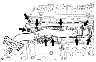 |
Remove the 9 nuts, exhaust manifold and 2 gaskets.
| 50. REMOVE STARTER COVER |
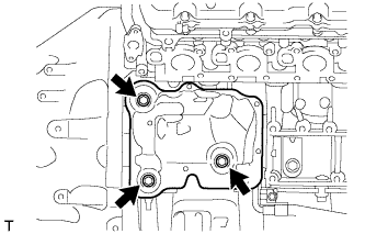 |
Remove the 3 bolts and starter cover.
| 51. REMOVE STARTER ASSEMBLY |
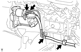 |
Disconnect the 2 wire harness clamps.
Disconnect the starter connector.
Remove the nut and disconnect the starter wire.
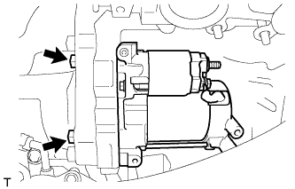 |
Remove the 2 bolts and starter.
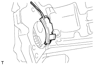 |
Remove the flywheel housing side cover.
| 52. REMOVE AUTOMATIC TRANSMISSION ASSEMBLY |
for 2WD:
Refer to the following procedures (Click here).
for 4WD:
Refer to the following procedures (Click here).
| 53. REMOVE REAR NO. 1 ENGINE MOUNTING INSULATOR (for 2WD) |
| 54. REMOVE REAR NO. 1 ENGINE MOUNTING INSULATOR (for 4WD) |
| 55. REMOVE DRIVE PLATE AND RING GEAR SUB-ASSEMBLY |
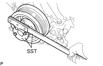 |
Using SST, hold the crankshaft.
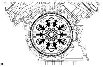 |
Remove the 10 bolts, rear drive plate spacer, drive plate and crankshaft angle sensor rotor.
| 56. REMOVE ENGINE ASSEMBLY |
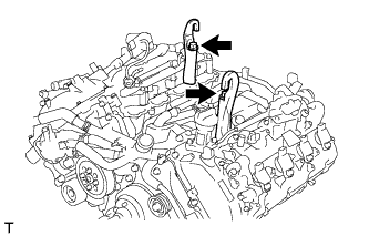 |
Install 2 engine hangers with 2 bolts as shown in the illustration.
| Engine hanger | 12281-38150 |
| Bolt | 90119-A0166 |
Attach an engine sling device and hang the engine with a chain block.
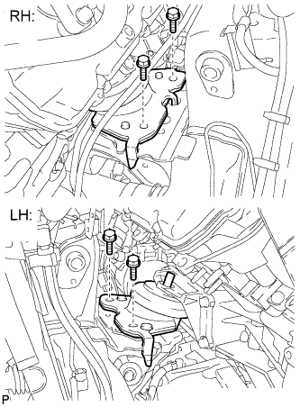 |
Remove the 4 engine mounting insulator bolts.
Lift the engine out from the vehicle slowly and carefully.
| 57. INSTALL ENGINE TO ENGINE STAND |
Install the engine to an engine stand with the bolts.
Remove the 2 bolts and 2 engine hangers.