Home › Engine / Hybrid System › CRUISE CONTROL › DYNAMIC LASER CRUISE CONTROL SYSTEM
RM27L0U _51 Engine / Hybrid System _049309 CRUISE CONTROL _0235640 DYNAMIC LASER CRUISE CONTROL SYSTEM J

CRUISE CONTROL  DYNAMIC LASER CRUISE CONTROL SYSTEM  Distance Control Switch Circuit  


DESCRIPTION

The distance control switch sets the vehicle-to-vehicle distance mode. The distance control switch is installed in the steering pad switch. The vehicle-to-vehicle distance set value can be changed by operating the steering pad switch (distance control switch) while the dynamic laser cruise control system is in operation.

WIRING DIAGRAM
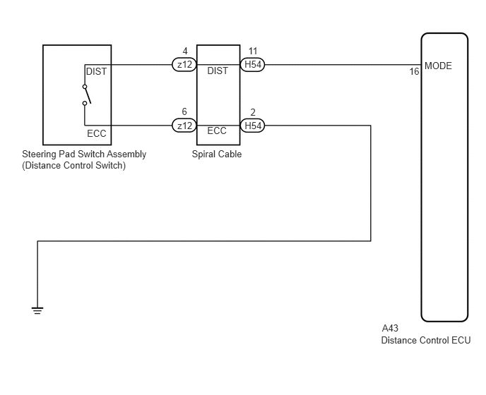
E162413E02
5.619,4.94 7.000,5.089 1.380,0.149 10 Distance Control ECU 5.634,4.761 5.902,4.910 0.268,0.149 10 A43 6.26,0.885 6.695,1.034 0.435,0.149 10 MODE 6.032,0.973 6.205,1.121 0.173,0.149 10 16 3.606,0.869 3.885,1.018 0.279,0.149 10 H54 3.659,0.668 3.832,0.817 0.173,0.149 10 11 3.608,1.771 3.882,1.920 0.274,0.149 10 H54 3.693,1.57 3.799,1.719 0.106,0.149 10 2 2.616,0.865 2.893,1.014 0.277,0.149 10 z12 2.692,0.664 2.794,0.813 0.102,0.149 10 4 2.617,1.767 2.860,1.916 0.243,0.149 10 z12 2.682,1.566 2.804,1.715 0.122,0.149 10 6 1.267,0.964 1.611,1.113 0.343,0.149 10 DIST 1.283,1.889 1.596,2.038 0.313,0.149 10 ECC 3.056,0.958 3.400,1.114 0.343,0.156 10 DIST 2.829,2.187 3.616,2.343 0.788,0.156 10 Spiral Cable 0.324,2.191 2.276,2.513 1.952,0.323 10 Steering Pad Switch Assembly (Distance Control Switch) 3.056,1.847 3.400,2.003 0.343,0.156 10 ECC

PROCEDURE

1.INSPECT STEERING PAD SWITCH ASSEMBLY
a.

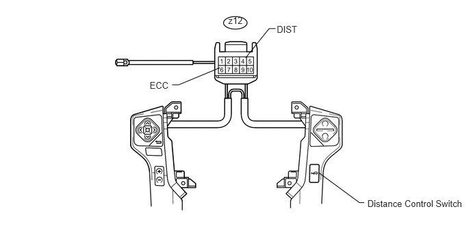
Remove the steering pad switch assembly (See page Steering>STEERING COLUMN>STEERING WHEEL>REMOVAL).
U154197E01
3.473,0.232 3.729,0.391 0.257,0.158 10 z12 4.193,0.436 4.094,0.436 4.094,0.436 3.737,0.881 false 2.62,1.292 2.72,1.292 2.72,1.292 3.346,1.032 false 4.211,0.367 4.559,0.523 0.349,0.156 10 DIST 2.277,1.223 2.602,1.371 0.324,0.149 10 ECC 5.59,3.019 7.105,3.190 1.515,0.171 10 Distance Control Switch 5.541,3.089 5.468,3.089 5.468,3.089 4.851,2.634 false


b.

Measure the resistance according to the value(s) in the table below.

Standard Resistance:
Tester Connection Switch Condition Specified Condition
z12-4 (DIST) - z12-6 (ECC) No switch is pushed 95 to 105 kΩ
Distance Control switch is pushed Below 2.5 Ω


HINT:

When a malfunction is detected in the distance control switch, replace the steering pad switch assembly.


OK

2.INSPECT SPIRAL CABLE

NG

REPLACE STEERING PAD SWITCH ASSEMBLY

2.INSPECT SPIRAL CABLE
NOTICE:

The spiral cable is an important part of the SRS airbag system. Incorrect removal or installation of the spiral cable may cause airbag deployment. Be sure to read the page shown in the brackets.


HINT:


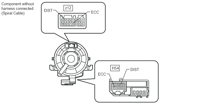
a.

Remove the spiral cable.

E345235E04
2.292,0.188 2.615,0.396 0.323,0.208 3.979,2.344 4.302,2.552 0.323,0.208 2.646,0.823 3.156,0.427 3.156,0.427 3.25,0.427 false 2.333,0.698 2,0.365 2,0.365 1.906,0.365 false 4.125,3.135 3.927,2.656 3.927,2.656 3.844,2.656 false 4.354,3.031 4.563,2.49 4.563,2.49 4.667,2.49 false 0.052,0.052 1.26,0.615 1.208,0.563 10 false Component without harness connected: (Spiral Cable) 2.344,0.198 2.802,0.396 0.458,0.198 10 false z12 4.031,2.365 4.49,2.563 0.458,0.198 10 false H54 3.531,2.583 3.99,2.781 0.458,0.198 10 false ECC 4.698,2.417 5.156,2.615 0.458,0.198 10 false DIST 1.583,0.292 1.896,0.448 0.313,0.156 10 false DIST 3.281,0.354 3.74,0.552 0.458,0.198 10 false ECC


b.

Measure the resistance according to the value(s) in the table below.

Standard Resistance:
Tester Condition Spiral Cable Position Specified Condition
z12-4 (DIST) - H54-11 (DIST) Center Below 1 Ω
2.5 rotations to the left
2.5 rotations to the right
z12-6 (ECC) - H54-2 (ECC) Center Below 1 Ω
2.5 rotations to the left
2.5 rotations to the right


HINT:

The spiral cable makes a maximum of approximately 5 rotations.


OK

3.CHECK HARNESS AND CONNECTOR (DISTANCE CONTROL ECU - SPIRAL CABLE)

NG

REPLACE SPIRAL CABLE

3.CHECK HARNESS AND CONNECTOR (DISTANCE CONTROL ECU - SPIRAL CABLE)
a.

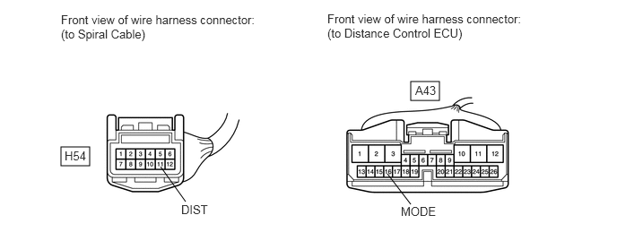
Disconnect the A43 distance control ECU connector.
E345249E01
0.708,1.708 1.042,1.927 0.333,0.219 4.771,0.948 5.104,1.167 0.333,0.219 1.865,1.938 2.156,2.344 false 4.5,2.021 4.771,2.375 false 0.708,0.146 2.958,0.5 2.25,0.354 10 false Front view of wire harness connector: (to Spiral Cable) 3.802,0.135 6.042,0.51 2.24,0.375 10 false Front view of wire harness connector: (to Distance Control ECU) 0.75,1.729 1.208,1.927 0.458,0.198 10 false H54 4.823,0.969 5.281,1.167 0.458,0.198 10 false A43 2.104,2.354 2.719,2.552 0.615,0.198 10 false DIST 4.656,2.375 5.271,2.573 0.615,0.198 10 false MODE


b.

Measure the resistance according to the value(s) in the table below.

Standard Resistance:
Tester Connection Condition Specified Condition
H54-11 (DIST) - A43-16 (MODE) Always Below 1 Ω
A43-16 (MODE) - Body ground Always 10 kΩ or higher


OK

4.CHECK HARNESS AND CONNECTOR (SPIRAL CABLE - BODY GROUND)

NG

REPAIR OR REPLACE HARNESS OR CONNECTOR

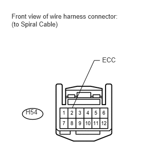
4.CHECK HARNESS AND CONNECTOR (SPIRAL CABLE - BODY GROUND)
a.
U154118E01
0.245,0.261 2.573,0.601 2.328,0.340 10 Front view of wire harness connector: (to Spiral Cable) 0.544,2.291 0.828,2.439 0.284,0.147 10 H54 2.168,1.19 2.523,1.340 0.355,0.150 10 ECC 2.12,1.282 1.999,1.282 1.999,1.282 1.535,2.284 false

Measure the resistance according to the value(s) in the table below.

Standard Resistance:
Tester Connection Condition Specified Condition
H54-2 (ECC) - Body ground Always Below 1 Ω


OK

5.INSPECT DISTANCE CONTROL ECU

NG

REPAIR OR REPLACE HARNESS OR CONNECTOR

5.INSPECT DISTANCE CONTROL ECU
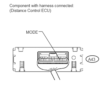
a.
U154119E02
1.313,1.073 1.438,1.073 1.438,1.073 2.042,2.031 false 0.323,0.104 2.625,0.458 2.302,0.354 10 false Component with harness connected: (Distance Control ECU) 3,1.938 3.281,2.094 0.281,0.156 10 false A43 0.885,1.01 1.333,1.156 0.448,0.146 10 false MODE

Remove the distance control ECU with the connector.


b.

Turn the ignition switch to ON.


c.

Measure the voltage according to the value(s) in the table below.

Standard Voltage:
Tester Connection Switch Condition Specified Condition
A43-16 (MODE) - Body ground Distance control switch ON Below 2 V
A43-16 (MODE) - Body ground Distance control switch OFF 11 to 14 V


OK

PROCEED TO NEXT CIRCUIT INSPECTION SHOWN IN PROBLEM SYMPTOMS TABLE

NG