DOOR / HATCH FRONT DOOR REASSEMBLY
CAUTION / NOTICE / HINT
- HINT:
- ·
Use the same procedure for the RH and LH sides.
·The procedure listed below is for the LH side.
PROCEDURE

 1.INSTALL PROTECTIVE CAP
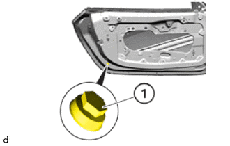
Install the protective cap (1).
2.INSTALL EXPANSION NUT
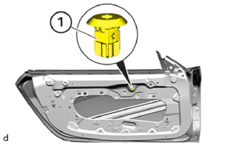
Install the expansion nut (1).
67866F
3.INSTALL NO. 3 FRONT DOOR WEATHERSTRIP
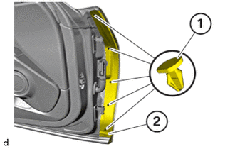
Insert No. 3 front door weatherstrip (2) and position correctly.
Mount clips (1).
82152
4.INSTALL FRONT DOOR WIRE
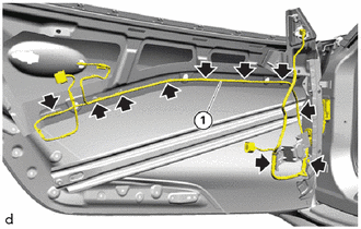
Clip in the front door wire (1) at the marked positions (arrows).
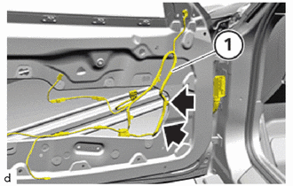
Clip in the front door wire (1) at the marked positions (arrows).
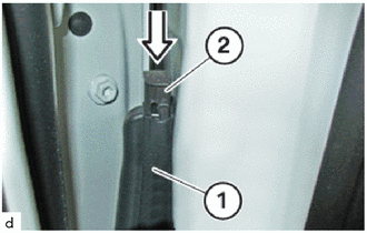
Connect connector (2) and lock.
Engage lock (1) in direction of arrow.
68620
5.INSTALL FRONT DOOR CHECK ASSEMBLY
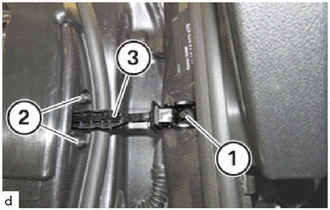
Slide in front door check assembly (3).
Tighten nuts (2).
- Torque:
- 8.0 N*m (82 kgf*cm, 71 in.*lbf)
Tighten down E10 bolt (1).
- Torque:
- 28.0 N*m (286 kgf*cm, 21 ft.*lbf)
69317A
6.INSTALL DOOR LOCK SPACER (for Driver Side)
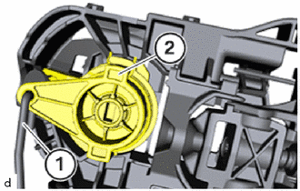
Connect the front door lock control link sub-assembly (1).
Install the lock cylinder (2) and turn it counter-clockwise.
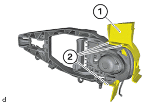
Install the door lock spacer (1).
Engage door lock spacer (1) at the detents (2).
69202A
7.INSTALL FRONT DOOR OUTSIDE HANDLE FRAME SUB-ASSEMBLY
69040A
8.INSTALL FRONT DOOR LOCK WITH MOTOR ASSEMBLY
69220
9.INSTALL FRONT DOOR OUTSIDE HANDLE ASSEMBLY
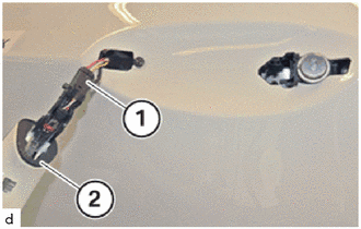
Connect connector (1) and lock.
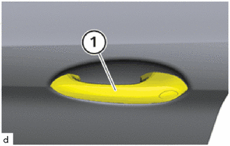
Insert the front door outside handle assembly (1).
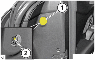
Tighten the clamping bolt (2) on the front door outside handle frame sub-assembly with the special tool 2 450 364.
- SST
- 09800-WA230
Install seal plug (1).
68193C
10.INSTALL FRONT DOOR BELT FRONT SEAL
Lightly coat the front door belt front seal with water.
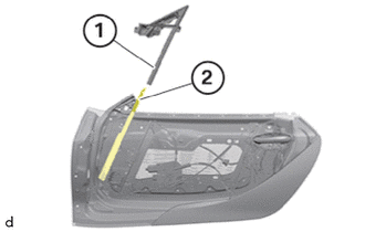
From above, insert the front door belt front seal (1) into the window guide rail (2).
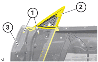
Clip the mounting elements (1) for the front door belt front seal (2) into the front door panel sub-assembly (3).
Make sure the front door belt front seal (2) is correctly seated.
67496C
11.INSTALL FRONT DOOR FRONT LOWER FRAME UPPER COVER
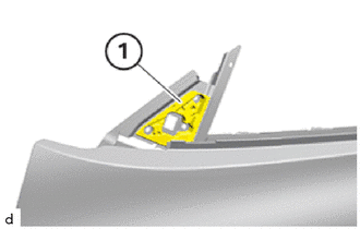
Install the front door front lower frame upper cover (1).
87940
12.INSTALL OUTER REAR VIEW MIRROR ASSEMBLY
13.INSTALL FRONT DOOR LOWER FRAME BRACKET GARNISH
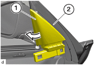
Install front door front door lower frame bracket garnish (1) on door (2) and connect it in the direction of the arrow.
69820
14.INSTALL FRONT DOOR WINDOW REGULATOR ASSEMBLY
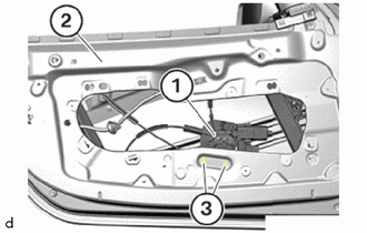
Thread front door window regulator assembly (1) into the front door panel sub-assembly (2) and position correctly.
Tighten nuts (3).
- Torque:
- 9.2 N*m (94 kgf*cm, 81 in.*lbf)
Connect front door window regulator assembly (1) to relevant plug connections and lock.
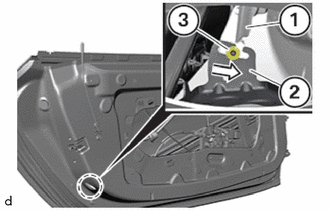
Push front door window regulator assembly (1) in arrow direction up to the stop onto the retaining plate (2).
Tighten nut (3).
- Torque:
- 9.2 N*m (94 kgf*cm, 81 in.*lbf)
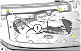
Tighten nuts (1) with special tool 0 496 726 (51 0 400). While doing so, hold the bolt.
- SST
- 09800-WA110
- Torque:
- 9.2 N*m (94 kgf*cm, 81 in.*lbf)
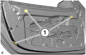
Install seal plug (1).
68102
15.INSTALL FRONT DOOR GLASS SUB-ASSEMBLY
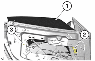
Guide the front door glass sub-assembly (1) from above into the front door panel sub-assembly.
Screw in and tighten multi-tooth screws (2) and (3) on the front door glass sub-assembly (1) so the front door glass sub-assembly can still be moved.
68102
16.ADJUST FRONT DOOR GLASS SUB-ASSEMBLY
The front door glass sub-assembly is all the way up.
Open front door.
Remove the seal plug (1).
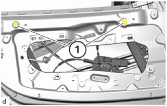
Release the nuts (1) on the front door glass sub-assembly with the special tool 0 496 726 (51 0 400). While doing so, hold the bolt.
- SST
- 09800-WA110
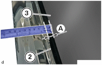
Measure the window cavity dimension (A) between the front door glass sub-assembly (3) and the door outer skin (2) at inner.
- Front door glass sub-assembly:
Area Measurement (A) 10.6 mm (0.417 in.)
- HINT:
-
Adjust the front door glass sub-assembly parallel to the door outer skin.
Adjust window cavity dimension by turning the bolt (1) on the power window using special tool 0 496 726 (51 0 400).
- SST
- 09800-WA110
Tighten the nuts (1) on the front door glass sub-assembly with the special tool 0 496 726 (51 0 400). While doing so, hold the bolt.
- SST
- 09800-WA110
- Torque:
- 9.2 N*m (94 kgf*cm, 81 in.*lbf)
Install seal plug (1).
68172A
17.INSTALL FRONT DOOR GLASS INNER WEATHERSTRIP
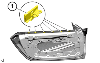
Install the clamps (1).
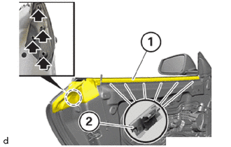
Correctly position the front door glass inner weatherstrip (1) and engage in the clamps (2).
Clip in the mounting elements (arrows).
18.INSTALL SOUND INSULATION
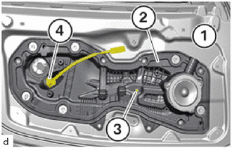
Correctly position the front door inside locking lock and unlock knob cable (4) in the sound insulation (2) and install.
Correctly position the sound insulation (2) on the front door panel sub-assembly (1).
Tighten nut (3).
- Torque:
- 9.2 N*m (94 kgf*cm, 81 in.*lbf)
Connect and lock all the corresponding connectors.
Fasten the mounting clip of the vehicle wiring harness on the sound insulation (2).
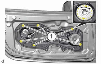
Lock the locks (1) in the direction of the arrow.
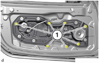
Tighten the T30 bolts (1).
- Torque:
- 8.0 N*m (82 kgf*cm, 71 in.*lbf)
86160
19.INSTALL FRONT NO. 1 SPEAKER ASSEMBLY
20.INSTALL SIDE AIRBAG PRESSURE SENSOR
86160P
21.INSTALL FRONT NO. 2 SPEAKER ASSEMBLY (w/ Front No. 2 Speaker)
84820
22.INSTALL POWER WINDOW REGULATOR MASTER SWITCH ASSEMBLY (for Driver Side)
84810
23.INSTALL POWER WINDOW REGULATOR SWITCH ASSEMBLY (for Front Passenger Side)
84840
24.INSTALL LUGGAGE COMPARTMENT DOOR OPENING SWITCH ASSEMBLY (for Driver Side)
84930
25.INSTALL DOOR CONTROL SWITCH ASSEMBLY
69272D
26.INSTALL FRONT DOOR INSIDE HANDLE
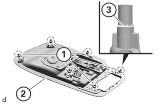
Saw off all the marked welding pins (1) on front door inside handle (2) along moulding (3).
Remove the welding residue on front door trim board sub-assembly with a scalpel.
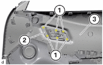
Position front door inside handle (2) correctly in front door trim board sub-assembly (3).
Make sure that the welding pins do not protrude through the front door trim board sub-assembly.
Tighten repair T20 screws (1) on front door inside handle (2).
- Torque:
- 2.3 N*m (23 kgf*cm, 20 in.*lbf)
67602
27.INSTALL FRONT DOOR TRIM BOARD SUB-ASSEMBLY
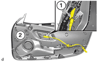
Correctly position the front door inside locking lock and unlock knob cable (1) on the front door trim board sub-assembly (2) and lock in.
Connect and engage all related plug connections for the front door trim board sub-assembly (2).
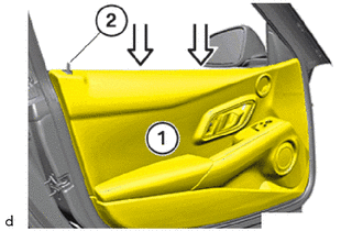
Insert the lock button (2) in the guide of the front door trim board sub-assembly (1).
Insert front door trim board sub-assembly (1) and position correctly.
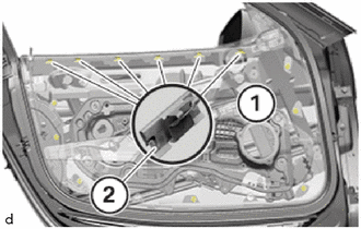
Correctly position front door trim board sub-assembly (1) and clip into the clamps (2).
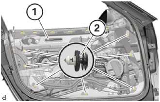
Correctly position front door trim board sub-assembly (1) and clip into the clips (2).
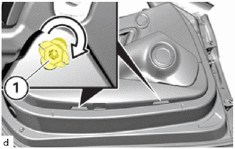
Lock the locks (1) in the direction of the arrow.
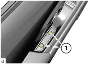
Tighten the T20 screws (1).
- Torque:
- 3.0 N*m (31 kgf*cm, 27 in.*lbf)
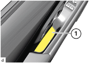
Correctly position and install door trim cover (1).
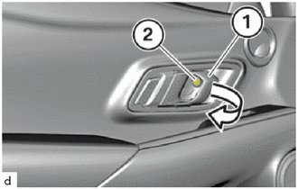
Press and hold door opener (1) in the arrow direction.
Tighten down T20 screw (2).
- Torque:
- 3.0 N*m (31 kgf*cm, 27 in.*lbf)
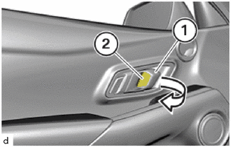
Press and hold door opener (1) in the arrow direction.
Correctly position and install No. 2 door inside handle bezel (2).
81230
28.INSTALL COURTESY LIGHT ASSEMBLY (w/ Courtesy Light)
29.CONNECT CABLE TO NEGATIVE BATTERY TERMINAL
for B48:
for B58:
68102
30.ADJUST FRONT DOOR GLASS SUB-ASSEMBLY
Open front door.
Move front door glass sub-assembly into uppermost position.
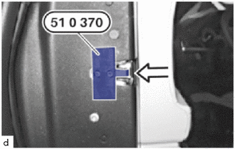
Insert special tool 0 496 693 (51 0 370) in the front door lock with motor assembly and lock the front door lock with motor assembly manually as shown in the illustration.
- SST
- 09800-WA330
Carefully close the front door until the special tool 0 496 693 (51 0 370) magnetically sticks to the front door lock striker plate assembly (defined opening angle for the measurement).
- SST
- 09800-WA330
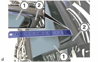
Measure approx. 30 mm (1.181 in.) forwards from the corner of the front door glass sub-assembly (1).
- NOTICE:
-
Do not exert any force on the front door or front door glass sub-assembly during measurement.
Determine dimension for preload between the front door opening trim weatherstrip (2) and outer edge of front door glass sub-assembly (1).
- Nominal dimension:
58 to 60 mm (2.28 to 2.36 in.)
Open front door and remove seal plug.
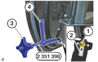
Feed in special tool 2 351 398 into the front door and position at the nut (1) and the guide (2).
- SST
- 09800-WA320
Loosen nut (1) with knob (3).
Adjust the preload by turning the lever (4).
- Nominal dimension:
58 to 60 mm (2.28 to 2.36 in.)
Tighten nut (1).
- Torque:
- 9.2 N*m (94 kgf*cm, 81 in.*lbf)
Check setting, repeat process if necessary.
Remove special tool 2 351 398 and mount the seal plug.
- SST
- 09800-WA320
Remove special tool 0 496 693 (51 0 370) from the front door lock with motor assembly.
- SST
- 09800-WA330
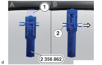
Have the special tool 2 356 862 ready.
- SST
- 09800-WA220
- HINT:
- ·
Illustration (A): locked state. This is how special tool 2 356 862 is connected to the front door glass sub-assembly with the bracket (1).
·Illustration (B): After closing the front door, the lock (2) is disengaged.
Open front door.
Connect special tool 2 356 862 to front door glass sub-assembly.
- SST
- 09800-WA220
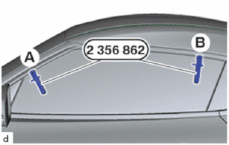
Position special tool (A) approx. 30 mm (1.181 in.) behind the mirror triangle.
- SST
- 09800-WA220
Position special tool (B) approx. 100 mm (3.937 in.) in front of the corner of the side glass sub-assembly.
- SST
- 09800-WA220
Close front door.
Loosen the lock.
Measure retraction depth with special tools (A) and (B).
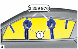
Mount special tool 2 359 976 on the front door glass sub-assembly leaving access to the multi-tooth screws of the front door glass sub-assembly.
- SST
- 09800-WA120
Release the adjustment lever (1) by rotating it.
Shift the adjustment lever (1) to adjust the retraction depth of the front door glass sub-assembly.
- Front door glass sub-assembly:
Area Measurement Retraction depth (A) 3.2 to 5.2 mm (0.126 to 0.205 in.) Retraction depth (B) 3.0 to 5.0 mm (0.118 to 0.197 in.)
Tighten adjustment lever (1).
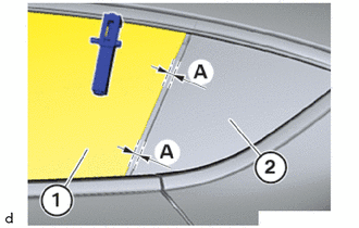
Adjust front door glass sub-assembly (1) parallel to the quarter window assembly (2).
- Front door glass sub-assembly:
Area Measurement (A) 7.0 to 9.0 mm (0.276 to 0.354 in.)
68102
31.TIGHTEN FRONT DOOR GLASS SUB-ASSEMBLY
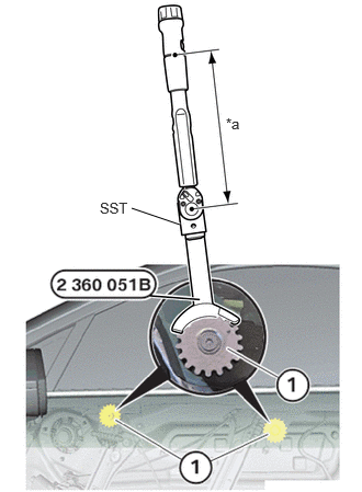
| *a | Torque Wrench Fulcrum Length |
Tighten multi-tooth bolts (1) on the front door glass sub-assembly with the special tool 2 360 051 (B) and SST, a torque wrench.
- SST
- 09800-WA130 09900-WA280
- Torque:
- Specified tightening torque: : 9.0 N*m (92 kgf*cm, 80 in.*lbf)
- HINT:
-
Calculate the torque wrench reading when changing the fulcrum length of the torque wrench.
-
Click hereGeneral>INTRODUCTION>REPAIR INSTRUCTION>PRECAUTION
75720
32.INSTALL FRONT DOOR BELT MOULDING ASSEMBLY
75072A
33.INSTALL FRONT DOOR OUTSIDE MOULDING SUB-ASSEMBLY
67862
34.INSTALL FRONT DOOR WEATHERSTRIP
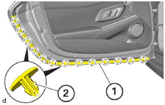
Position the front door weatherstrip (1) on the front door panel sub-assembly and clip in at the clips (2).