REAR SUSPENSION REAR SUSPENSION MEMBER BODY MOUNTING CUSHION INSTALLATION
CAUTION / NOTICE / HINT
- NOTICE:
- ·
Damage to the rear suspension member sub-assembly.
Non-observance of the pull-out and pull-in direction of the rear suspension member body mounting cushion will damage the rear suspension member sub-assembly.
-Adherence to the pull-out and pull-in direction is absolutely mandatory.
PROCEDURE

 52271
1.INSTALL REAR SUSPENSION MEMBER CUSHION
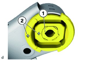
Make sure that the notch (1) and the arrows (2) of the rear suspension member cushion point in the direction of travel.
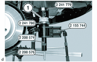
Insert the rear suspension member cushion (1) up to the limit position with the special tools 2 241 779, 2 155 744, 2 241 780, 2 208 574 and 2 208 576 .
- SST
- 09500-WA130
09500-WA140
09500-WA220
09600-WA020
Remove special tools for inserting rear suspension member cushion (1).
52271D
2.INSTALL REAR SUSPENSION MEMBER BODY MOUNTING FRONT CUSHION
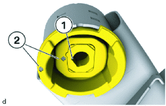
Make sure that the notch (1) and the arrows (2) of the rear suspension member body mounting front cushion point in the direction of travel.
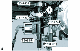
Insert the rear suspension member body mounting front cushion (1) up to limit position with the special tools 0 494 971 (33 4 432), 0 494 972 (33 4 433), 2 155 744, 2 208 574 and 2 208 576.
- SST
- 09500-WA220
09500-WA250
09600-WA020
Remove special tools for inserting rear suspension member body mounting front cushion (1).
51206A
3.INSTALL REAR SUSPENSION MEMBER SUB-ASSEMBLY
- HINT:
-
Perform the operations on the left and right side.
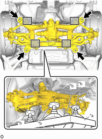
| *a | Engine Lifter |
| *b | Attachment |

|
Attachment and Wooden Block Placement Location |
Using an engine lifter and 4 attachments or equivalent tools, support the rear suspension member sub-assembly as shown in the illustration.
- CAUTION:
- ·
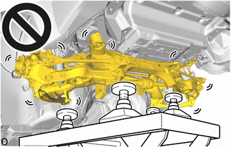
·The rear suspension member sub-assembly is a very heavy component. Make sure that it is supported securely.
·If the rear suspension member sub-assembly is not securely supported, it may drop, resulting in serious injury.
- NOTICE:
- ·
Use attachments and wooden blocks to keep the rear suspension member sub-assembly level.
·Keep supporting the rear suspension member sub-assembly until the installation has been completed.
Raise the rear suspension member sub-assembly until there is no clearance between the rear suspension member sub-assembly and vehicle.
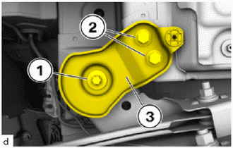
Position rear suspension member rear lower brace LH (3).
Replace E18 (1) bolt and 16 mm bolts (2).
Tighten down 16 mm bolts (2).
- Torque:
- 47 N*m (479 kgf*cm, 35 ft.*lbf)
Using SST, tighten the 16 mm bolt (2) an additional 45°.
- SST
- 09900-WA010
- HINT:
- ·
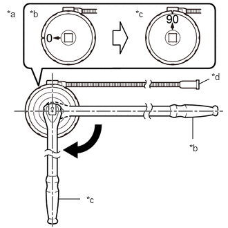 2.99,1.271 3.156,1.188 false 2.906,2.094 2.906,1.76 false 0.875,3 1.208,3 false 0.104,0.125 0.417,0.281 0.313,0.156 10 false *a 0.448,0.125 0.76,0.281 0.313,0.156 10 false *b 2.042,0.125 2.354,0.281 0.313,0.156 10 false *c 3.188,1.073 3.427,1.271 0.24,0.198 10 false *d 2.854,2.146 3.167,2.302 0.313,0.156 10 false *b 1.302,2.927 1.615,3.083 0.313,0.156 10 false *c
*a Example *b Before Tightening *c After Tightening *d Magnetic Portion
·The magnetic portion is used to secure the gauge to the vehicle.
·After first adjusting the needle of the gauge to 0°, tighten to the specified angle.
·Perform the work procedure carefully so that the gauge, etc. does not become tilted.
Tighten down E18 bolt (1).
- Torque:
- 108 N*m (1101 kgf*cm, 80 ft.*lbf)
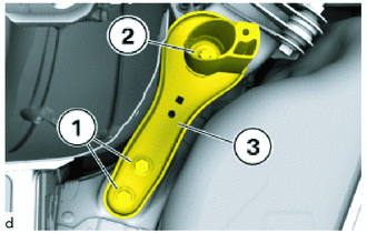
Position rear lower suspension member stopper LH (3).
Replace 16 mm bolts (1) and E18 bolt (2).
Tighten the 16 mm bolts (1).
- Torque:
- 47 N*m (479 kgf*cm, 35 ft.*lbf)
Using SST, tighten the 16 mm bolt (1) an additional 45°.
- SST
- 09900-WA010
- HINT:
- ·
2.99,1.271 3.156,1.188 false 2.906,2.094 2.906,1.76 false 0.875,3 1.208,3 false 0.104,0.125 0.417,0.281 0.313,0.156 10 false *a 0.448,0.125 0.76,0.281 0.313,0.156 10 false *b 2.042,0.125 2.354,0.281 0.313,0.156 10 false *c 3.188,1.073 3.427,1.271 0.24,0.198 10 false *d 2.854,2.146 3.167,2.302 0.313,0.156 10 false *b 1.302,2.927 1.615,3.083 0.313,0.156 10 false *c
*a Example *b Before Tightening *c After Tightening *d Magnetic Portion
·The magnetic portion is used to secure the gauge to the vehicle.
·After first adjusting the needle of the gauge to 0°, tighten to the specified angle.
·Perform the work procedure carefully so that the gauge, etc. does not become tilted.
Tighten down E18 bolt (2).
- Torque:
- 108 N*m (1101 kgf*cm, 80 ft.*lbf)
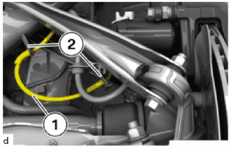
Attach the cable of the parking brake (1) in the holders (2).
w/ LSD:
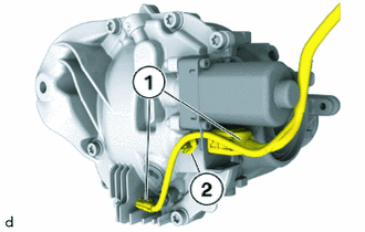
Connect connectors (1) and lock.
Attach the cable clip (2).
Connect the ground wire with the bolt.
- Torque:
- 8.0 N*m (82 kgf*cm, 71 in.*lbf)
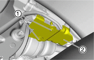
Install the rear differential protector (2) with the bolts (1).
- Torque:
- 4.5 N*m (46 kgf*cm, 40 in.*lbf)
4.INSTALL REAR COIL SPRING LH
5.INSTALL REAR COIL SPRING RH
- HINT:
-
Use the same procedure as for the LH side.
37100
6.INSTALL PROPELLER SHAFT WITH CENTER BEARING ASSEMBLY
7.INSTALL WIRE HARNESS
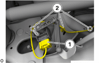
Connect connector (1) and lock.
Route wire harness of the rear height control sensor sub-assembly through brackets (2).
8.INSTALL REAR FLEXIBLE HOSE LH
Feed rear flexible hose LH into the holder.
- NOTICE:
-
Make sure that the rear flexible hose LH does not rest against the components fixed to the body and that it is not twisted.
9.INSTALL REAR FLEXIBLE HOSE RH
- HINT:
-
Use the same procedure as for the LH side.
10.INSTALL PAD WEAR INDICATOR WIRE ASSEMBLY (for RH Side)
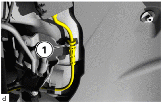
Attach cable of pad wear indicator wire assembly in the holders (1).
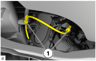
Attach cable of pad wear indicator wire assembly in the holders (1).
89516P
11.INSTALL REAR SKID CONTROL SENSOR WIRE LH
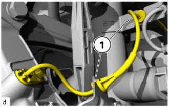
Connect the cable of the rear skid control sensor wire LH in the brackets (1).
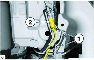
Connect the cable of the rear skid control sensor wire LH in the brackets (1).
Connect connector (2) and lock.
89516N
12.INSTALL REAR SKID CONTROL SENSOR WIRE RH
- HINT:
-
Use the same procedure as for the LH side.
65638
13.INSTALL REAR WHEEL HOUSE LINER LH
- HINT:
-
Use the same procedure as for the RH side.
65637
14.INSTALL REAR WHEEL HOUSE LINER RH
48738
15.INSTALL REAR SUSPENSION ARM COVER LH
48737
16.INSTALL REAR SUSPENSION ARM COVER RH
- HINT:
-
Use the same procedure as for the LH side.
17.INSTALL REAR WHEEL
18.INSPECT AND ADJUST REAR WHEEL ALIGNMENT