SFI SYSTEM > EVAP System |
| DTC No. | Monitoring Items | See procedure |
| P043E | Reference orifice clogged (built into canister pump module) |
Click here
|
| P043F | Reference orifice high-flow (built into canister pump module) | |
| P0441 |
|
Click here
|
| P0450 | Canister pressure sensor (built into canister pump module) voltage abnormal fluctuation |
Click here
|
| P0451 |
| |
| P0452 | Canister pressure sensor (built into canister pump module) voltage low | |
| P0453 | Canister pressure sensor (built into canister pump module) voltage high | |
| P0455 | EVAP gross leak |
Click here
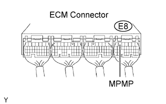
|
| P0456 | EVAP small leak | |
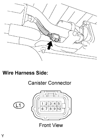
| P2401 | Leak detection pump stuck OFF (built into canister pump module) |
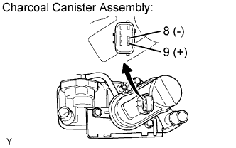
Click here
|
| P2402 | Leak detection pump stuck ON (built into canister pump module) | |
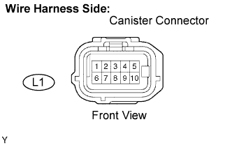
| P2419 | Vent valve stuck closed (built into canister pump module) |
Click here
|
| P2420 | Vent valve stuck open (vent) (built into canister pump module) | |
| P2610 | Soak timer (built into ECM) |
Click here
|
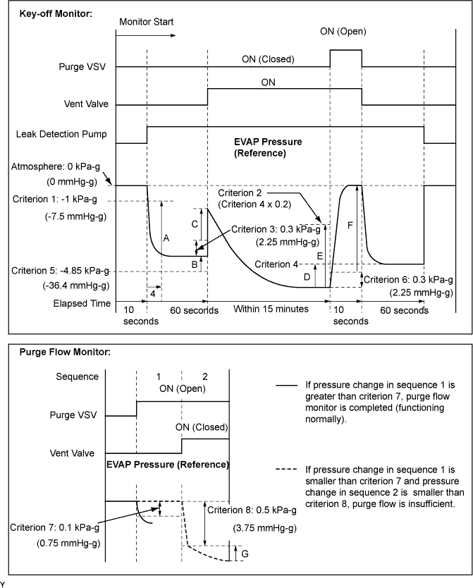
| Key-off monitor |
| Purge flow monitor |
| Components | Operations |
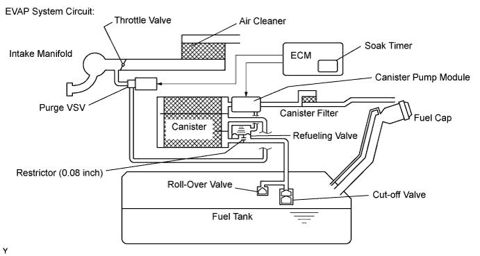
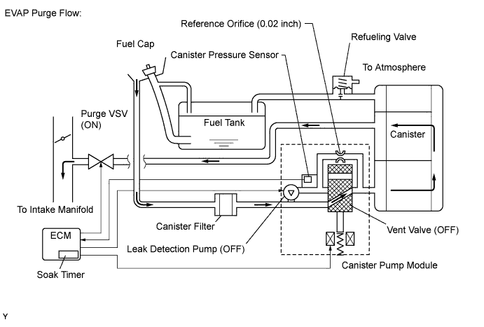
| Canister | Contains activated charcoal to absorb EVAP (Evaporative Emissions) generated in fuel tank. |
| Cut-off valve | Located in fuel tank. Valve floats and closes when fuel tank 100 % full. |
| Purge VSV (Vacuum Switching Valve) | Opens or closes line between canister and intake manifold. ECM uses purge VSV to control EVAP purge flow. In order to discharge EVAP absorbed by canister to intake manifold, ECM opens purge VSV. EVAP discharge volume to intake manifold controlled by purge VSV duty cycle ratio (current-carrying time). (Open: ON, Close: OFF) |
| Refueling valve | Controls EVAP pressure from fuel tank to canister. Valve consists of diaphragm, spring and restrictor (diameter: 0.08 inch). When fuel vapor and pressure inside fuel tank increase, valve opens. While EVAP purged, valve closes and restrictor prevents large amount of vacuum from affecting pressure in fuel tank. Valve opened while refueling. When valve open, adding fuel into fuel tank possible. |
| Roll-over valve | Located in fuel tank. Valve closes by its own weight when vehicle overturns to prevent fuel from spilling out. |
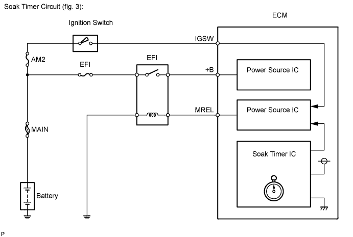
| Soak timer | Built into ECM. To ensure accurate EVAP monitor, measures 5 hours (+- 15 min) after ignition switch turned to OFF. This allows fuel to cool down, stabilizing Fuel Tank Pressure (FTP). When approximately 5 hours elapsed, ECM activates. |
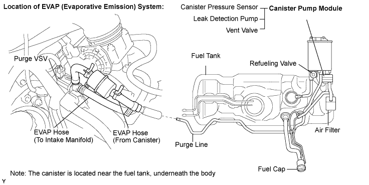
| Canister pump module | Consists of (a) to (d) below. Canister pump module cannot be disassembled. |
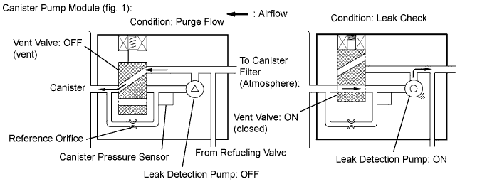
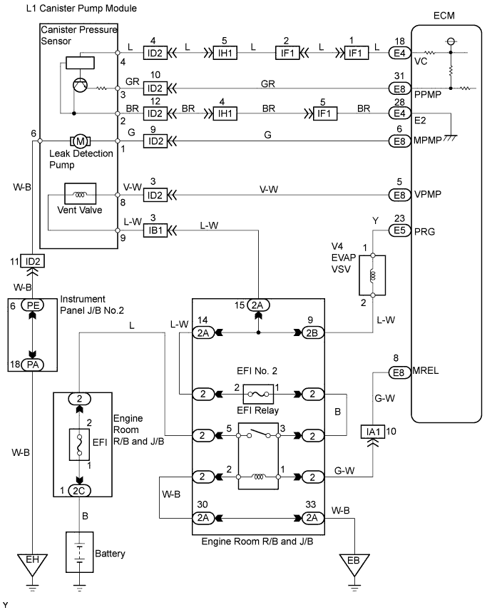
| (a) Vent valve | Vents and closes EVAP system. When ECM turns valve ON, EVAP system closed. When, ECM turns valve OFF, EVAP system vented. Negative pressure (vacuum) created in EVAP system to check for EVAP leaks by closing purge VSV, turning on vent valve (closed) and operating leak detection pump (refer to fig. 1). |
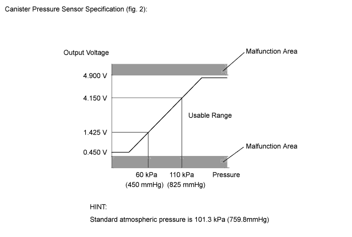
| (b) Canister pressure sensor | Indicates pressure as voltages. ECM supplies regulated 5 V to canister pressure sensor, and uses feedback from sensor to monitor EVAP system pressure (refer to fig 2). |
| (c) Leak detection pump | Creates negative pressure (vacuum) in EVAP system for leak check. |
| (d) Reference orifice | Has opening with 0.02 inch diameter. Vacuum produced through orifice by closing purge VSV, turning off vent valve and operating leak detection pump, to monitor 0.02 inch leak criterion. 0.02 inch leak criterion indicates small leak of EVAP. |
| 1.CONFIRM DTC |
Turn the ignition switch to OFF and wait for 10 seconds.
Turn the ignition switch to ON.
Turn the ignition switch to OFF and wait for 10 seconds.
Connect an intelligent tester to the DLC3.
Turn the ignition switch to ON and turn the tester ON.
Select the following menu items: DIAGNOSIS / ENHANCED OBD II / DTC INFO / CURRENT CODES.
Confirm DTCs and freeze frame data.
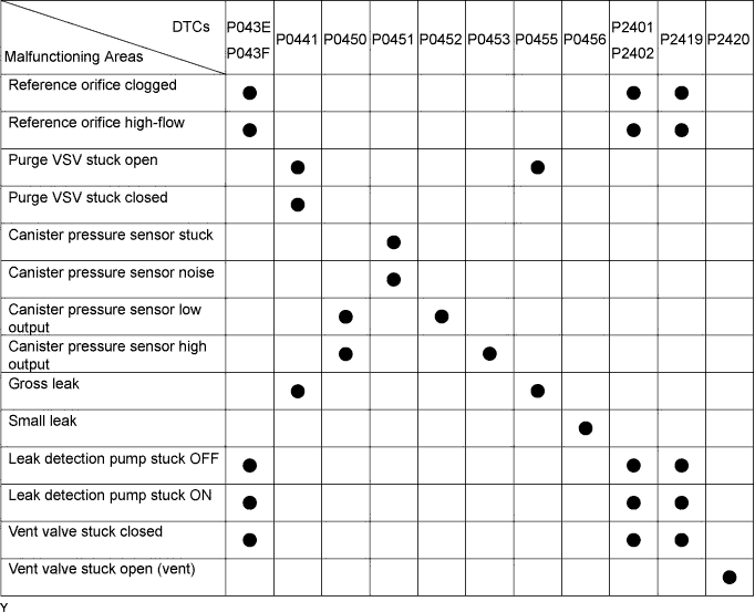
If any EVAP system DTCs are set, the malfunctioning area can be determined using the table below.
| NEXT | |
 |
| 2.PERFORM EVAP SYSTEM CHECK (AUTO OPERATION) |
Clear DTCs (Click here).
On the tester, select the following menu items: DIAGNOSIS / ENHANCED OBD II / SYSTEM CHECK / EVAP SYS CHECK / AUTO OPERATION.
After the EVAP SYSTEM CHECK is completed, check for pending DTCs by selecting the following menu items: DIAGNOSIS / ENHANCED OBD II / DTC INFO / PENDING CODES.
| NEXT | |
|
| 3.PERFORM EVAP SYSTEM CHECK (MANUAL OPERATION) |
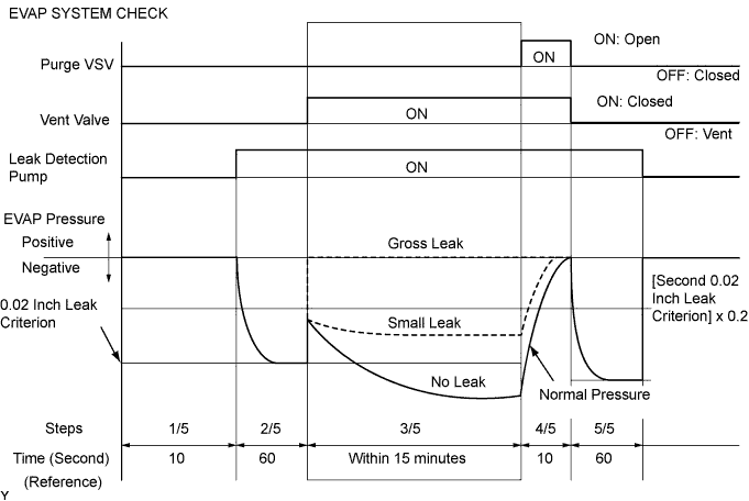
Clear DTCs (Click here).
Select the following menu items: DIAGNOSIS / ENHANCED OBD II / SYSTEM CHECK / EVAP SYS CHECK / MANUAL OPERATION.
| NEXT | |
|
| 4.PERFORM EVAP SYSTEM CHECK (STEP 1/5) |
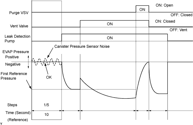
Check the EVAP pressure in step 1/5.
| DTCs*
| Test Results | Suspected Trouble Areas | Proceed To |
| - | Virtually no variation in EVAP pressure | Not yet determined | A |
| P0451 | EVAP pressure fluctuates by +-0.3 kPa (2.25 mmHg) or more | Canister pressure sensor noise | B |
|
| ||||
| A | |
|
| 5.PERFORM EVAP SYSTEM CHECK (STEP 1/5 TO 2/5) |
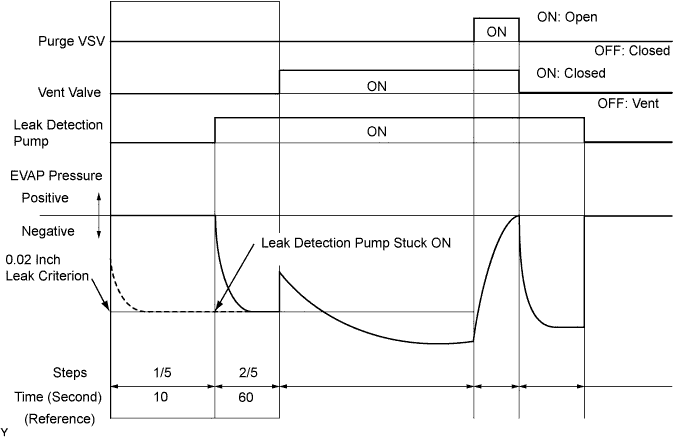
Check the EVAP pressure in step 1/5 and 2/5.
| DTCs*
| Test Results | Suspected Trouble Areas | Proceed To |
| - | Virtually no variation in EVAP pressure during step 1/5. Then decreases to 0.02 inch leak criterion | Not yet determined | A |
| P2402 | Small difference between EVAP pressures during steps 1/5 and 2/5 | Leak detection pump stuck ON | B |
|
| ||||
| A | |
|
| 6.PERFORM EVAP SYSTEM CHECK (STEP 2/5) |
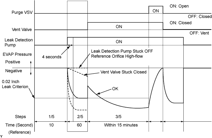
Check the EVAP pressure 4 seconds after the leak detection pump is activated*.
Check the EVAP pressure again when it has stabilized. This pressure is the 0.02 inch leak criterion.
*: The leak detection pump begins to operate as step 1/5 is proceeded to step 2/5.
| DTCs*
| Test Results | Suspected Trouble Areas | Proceed To |
| - | EVAP pressure in step (b) between -4.85 kPa and -1.06 kPa (-36.38 mmHg and -7.95 mmHg) | Not yet determined | A |
| P043F and P2401 | EVAP pressure in step (b) -1.06 kPa (-7.95 mmHg) or more |
| B |
| P043E | EVAP pressure in step (b) below -4.85 kPa (-36.38 mmHg) | Reference orifice clogged | C |
| P2419 | EVAP pressure in step (a) more than -1.06 kPa (-7.95 mmHg) | Vent valve stuck closed | D |
|
| ||||
|
| ||||
|
| ||||
| A | |
|
| 7.PERFORM EVAP SYSTEM CHECK (STEP 2/5 TO 3/5) |
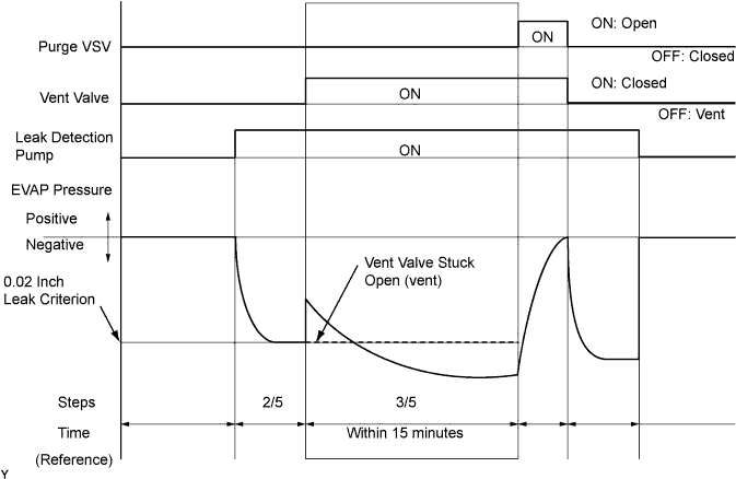
Check the EVAP pressure increase in step 3/5.
| DTCs*
| Test Results | Suspected Trouble Areas | Proceed To |
| - | EVAP pressure increases by 0.3 kPa (2.25 mmHg) or more within 10 seconds of proceeding from step 2/5 to step 3/5 | Not yet determined | A |
| P2420 | No variation in EVAP pressure despite proceeding from step 2/5 to step 3/5 | Vent valve stuck open (vent) | B |
| P0451 | No variation in EVAP pressure during steps 1/5 through 3/5 | Canister pressure sensor malfunction stuck | C |
|
| ||||
|
| ||||
| A | |
|
| 8.PERFORM EVAP SYSTEM CHECK (STEP 3/5) |
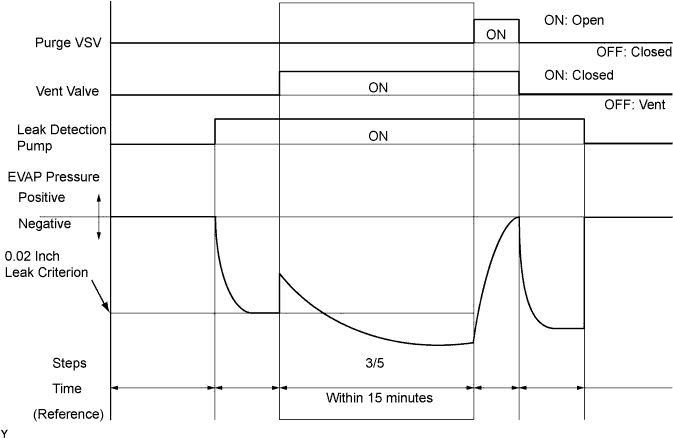
Wait until the EVAP pressure change is less than 0.1 kPa (0.75 mmHg) for 30 seconds.
Measure the EVAP pressure and record it.
| NEXT | |
|
| 9.PERFORM EVAP SYSTEM CHECK (STEP 4/5) |
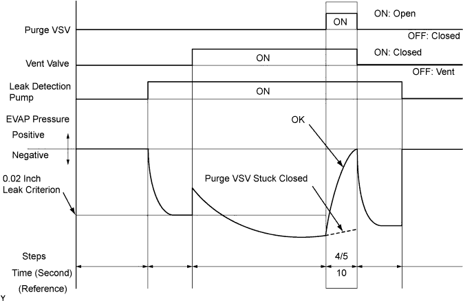
Check the EVAP pressure in step 4/5.
| DTCs*
| Test Results | Suspected Trouble Areas | Proceed To |
| - | EVAP pressure increases by 0.3 kPa (2.25 mmHg) or more within 10 seconds of proceeding from step 3/5 to step 4/5 | Not yet determined | A |
| P0441 | EVAP pressure increases by 0.3 kPa (2.25 mmHg) or more within 10 seconds of proceeding from step 3/5 to step 4/5 | Problems in EVAP hose between pure VSV and intake manifold | B |
| P0441 | Variation in EVAP pressure less than 0.3 kPa (2.25 mmHg) for 10 seconds, after proceeding from step 3/5 to step 4/5 | Purge VSV stuck closed | C |
|
| ||||
|
| ||||
| A | |
|
| 10.PERFORM EVAP SYSTEM CHECK (STEP 5/5) |
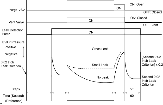
Check the EVAP pressure in step 5/5.
Compare the EVAP pressure in step 3/5 and the second 0.02 inch leak criterion (step 5/5).
| DTCs*
| Test Results | Suspected Trouble Areas | Proceed To |
| - | EVAP pressure (step 3/5) lower than second 0.02 inch leak criterion (step 5/5) | Not yet determined (no leakage from EVAP system) | A |
| P0441 and P0455 | EVAP pressure (step 3/5) higher than [second 0.02 inch leak criterion (step 5/5) x 0.2] |
| B |
| P0456 | EVAP pressure (step 3/5) higher than second 0.02 inch leak criterion (step 5/5) | EVAP small leak | B |
|
| ||||
|
| ||||
| 11.PERFORM EVAP SYSTEM CHECK (STEP 3/5) |
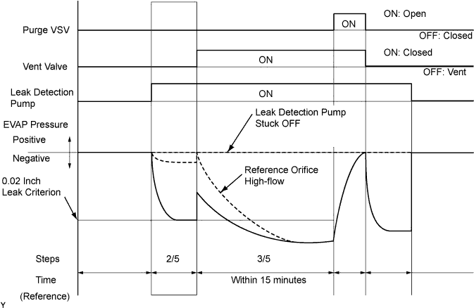
Check the EVAP pressure in step 3/5.
| DTCs*
| Test Results | Suspected Trouble Areas | Proceed To |
| P043F | EVAP pressure less than [0.02 inch leak criterion] measured at 2/5 | Reference orifice high-flow | A |
| P2401 | EVAP pressure almost same as [0.02 inch leak criterion] measured at 2/5 | Leak detection pump stuck OFF | B |
|
| ||||
|
| ||||
| 12.PERFORM ACTIVE TEST USING INTELLIGENT TESTER (PURGE VSV) |
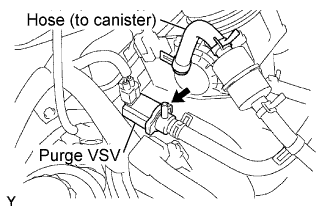 |
On the intelligent tester, select the following menu items: DIAGNOSIS / ENHANCED OBD II/ ACTIVE TEST / EVAP VSV.
Disconnect the hose (connected to the canister) from the purge VSV.
Start the engine.
Using the tester, turn off the purge VSV (EVAP VSV: OFF).
Use your finger to confirm that the purge VSV has no suction.
Using the tester, turn on the purge VSV (EVAP VSV: ON).
Use your finger to confirm that the purge VSV has suction.
| Test Results | Suspected Trouble Areas | Proceed To |
| No suction when Purge VSV turned OFF, and suction applied when turned ON | Purge VSV normal | A |
| Suction applied when purge VSV turned OFF | Purge VSV stuck open | B |
| No suction when purge VSV turned ON |
| C |
Reconnect the hose.
|
| ||||
|
| ||||
| A | |
|
| 13.CHECK FUEL CAP ASSEMBLY |
Check that the fuel cap is correctly installed.
Confirm that the fuel cap is tightened until a few click sounds are heard.
Remove the fuel cap and install it onto a fuel cap adaptor.
Connect an EVAP tester pump hose to the adaptor, and pressurize the cap to 3.2 to 3.7 kPa (24 to 28 mmHg) using an EVAP tester pump.
Seal the adaptor and wait for 2 minutes.
Check the pressure. If the pressure is 2 kPa (15 mmHg) or more, the fuel cap is normal.
Reinstall the fuel cap.
| Test Results | Suspected Trouble Areas | Proceed To |
| Fuel cap correctly installed | - | A |
| Fuel cap loose |
| B |
| No fuel cap | - | C |
|
| ||||
|
| ||||
|
| ||||
| 14.INSPECT DUTY VACUUM SWITCHING VALVE (PURGE VSV) |
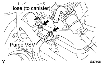 |
Turn the ignition switch to OFF.
Disconnect the V4 purge VSV connector.
Disconnect the hose (connected to the canister) from the purge VSV.
Start the engine.
Use your finger to confirm that the purge VSV has no suction.
| Test Results | Suspected Trouble Areas | Proceed To |
| No suction | ECM | A |
| Suction applied | Purge VSV | B |
Reconnect the purge VSV connector.
Reconnect the hose.
|
| ||||
|
| ||||
| 15.CHECK EVAP HOSE (PURGE VSV - INTAKE MANIFOLD) |
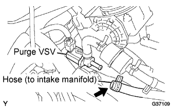 |
Disconnect the hose (connected to the intake manifold) from the purge VSV.
Start the engine.
Use your finger to confirm that the hose has suction.
| Test Results | Suspected Trouble Areas | Proceed To |
| Suction applied | EVAP hose between purge VSV and intake manifold normal | A |
| No suction |
| B |
Reconnect the hose.
|
| ||||
| A | |
|
| 16.INSPECT DUTY VACUUM SWITCHING VALVE (PURGE VSV) |
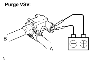 |
Remove the purge VSV.
Apply the battery voltage to the terminals of the purge VSV.
Using an air gun, confirm that air flows from port A to port B.
| Test Results | Suspected Trouble Areas | Proceed To |
| Air flows | Purge VSV normal | A |
| No air flow | Purge VSV | B |
Install the purge VSV.
|
| ||||
| A | |
|
| 17.CHECK HARNESS AND CONNECTOR (POWER SOURCE OF PURGE VSV) |
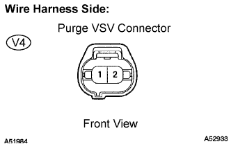 |
Disconnect the V4 purge VSV connector.
Turn the ignition switch to ON.
Measure the voltage between terminal 1 of the purge VSV connector and the body ground.
| Test Results | Suspected Trouble Areas | Proceed To |
| Between 11 V and 14 V | Normal | A |
| Other than result above | Wire harness or connectors between purge VSV and ECM | B |
Reconnect the purge VSV connector.
|
| ||||
| A | |
|
| 18.CHECK HARNESS AND CONNECTOR (PURGE VSV - ECM) |
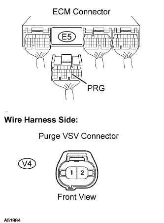 |
Disconnect the E5 ECM connector and the V4 purge VSV connector.
Check the resistance.
| Tester Connections | Specified Conditions |
| PRG (E5-23) - Purge VSV (V4-1) | Below 1 Ω |
| PRG (E5-23) - Body ground | 10 kΩ or higher |
| Purge VSV (V4-2) - Body ground | 10 kΩ or higher |
Reconnect the purge VSV connector.
Reconnect the ECM connector.
|
| ||||
|
| ||||
| 19.PERFORM ACTIVE TEST USING INTELLIGENT TESTER (FOR VENT VALVE) |
 |
Turn the ignition switch to ON.
On the intelligent tester, select the following menu items: DIAGNOSIS / ENHANCED OBD II / ACTIVE TEST / VENT VALVE (ALONE).
Measure the voltage between terminal VPMP of the ECM connector and the body ground when the vent valve is turned ON (close) and OFF (vent) using the tester.
| Test Results | Suspected Trouble Areas | Proceed To |
| Between 9 V and 14 V when OFF Below 3 V when ON | Vent valve | A |
| Below 3 V when OFF and ON | ECM | B |
|
| ||||
|
| ||||
| 20.PERFORM ACTIVE TEST USING INTELLIGENT TESTER (FOR VENT VALVE) |
|
Turn the ignition switch to ON.
On the intelligent tester, select the following menu items: DIAGNOSIS / ENHANCED OBD II / ACTIVE TEST / VENT VALVE (ALONE).
Measure the voltage between terminal VPMP of the ECM connector and the body ground when the vent valve is turned ON (close) and OFF (vent) using the tester.
| Test Results | Suspected Trouble Areas | Proceed To |
| Below 3 V when OFF and ON | Power source of vent valve | A |
| Between 9 V and 14 V when OFF Below 3 V when ON | Vent valve | B |
| Between 9 V and 14 V when OFF and ON | ECM | C |
|
| ||||
|
| ||||
| A | |
|
| 21.INSPECT CANISTER PUMP MODULE (POWER SOURCE FOR VENT VALVE) |
 |
Turn the ignition switch OFF.
Disconnect the L1 canister connector.
Turn the ignition switch to ON.
Measure the voltage between terminal 9 of the canister connector and the body ground.
| Test Results | Suspected Trouble Areas | Proceed To |
| Between 9 V and 14 V | Normal | A |
| Between 0 V and 3 V | Power source wire harness of vent valve | B |
Reconnect the canister connector.
|
| ||||
| A | |
|
| 22.INSPECT CANISTER PUMP MODULE (VENT VALVE OPERATION) |
 |
Turn the ignition switch to OFF.
Disconnect the L1 canister connector.
Apply the battery voltage to terminals 9 and 8 of the canister pump module.
Touch the canister pump module to confirm the vent valve operation.
| Test Results | Suspected Trouble Areas | Proceed To |
| Operating | Wire harness between vent valve and ECM | A |
| Not operating | Vent valve | B |
Reconnect the canister connector.
|
| ||||
|
| ||||
| 23.PERFORM ACTIVE TEST USING INTELLIGENT TESTER (FOR CANISTER PUMP MODULE (LEAK DETECTION PUMP)) |
|
On the intelligent tester, select the following menu items: DIAGNOSIS / ENHANCED OBD II / ACTIVE TEST / VACUUM PUMP (ALONE).
Measure the voltage between MPMP terminal of the ECM connector and the body ground when the leak detection pump is turned ON and OFF using the tester.
| Test Results | Suspected Trouble Areas | Proceed To |
| Between 0 V and 3 V when OFF Between 9 V and 14 V when ON | ECM normal | A |
| Between 9 V and 14 V when OFF Between 0 V and 3 V when ON | ECM | B |
|
| ||||
| A | |
|
| 24.CHECK HARNESS AND CONNECTOR (CANISTER PUMP MODULE - ECM) |
|
Turn the ignition switch to OFF.
Disconnect the L1 canister connector.
Turn the ignition switch to ON.
On the intelligent tester, select the following menu items: DIAGNOSIS / ENHANCED OBD II / ACTIVE TEST / VACUUM PUMP (ALONE).
Turn the leak detection pump ON.
Measure the voltage between terminal 1 of the canister connector and the body ground.
| Test Results | Suspected Trouble Areas | Proceed To |
| Between 9 V and 14 V | Normal | A |
| Between 0 V and 3 V | Wire harness between ECM and leak detection pump | B |
Reconnect the canister connector.
|
| ||||
| A | |
|
| 25.CHECK HARNESS AND CONNECTOR (CANISTER PUMP MODULE - GROUND) |
 |
Disconnect the L1 canister connector.
Turn the ignition switch to OFF.
Check the resistance between terminal 6 of the canister connector and the body ground.
| Test Results | Suspected Trouble Areas | Proceed To |
| Below 1 Ω | Leak detection pump | A |
| 10 kΩ or higher | Wire harness between leak detection pump and body ground | B |
Reconnect the canister connector.
|
| ||||
|
| ||||
| 26.INSPECT INTAKE MANIFOLD (EVAP PURGE PORT) |
Stop the engine.
Disconnect the EVAP hose from the intake manifold.
Start the engine.
Use your finger to confirm that the port of the intake manifold has suction.
| Test Results | Suspected Trouble Areas | Proceed To |
| Suction applied | EVAP hose between intake manifold and purge VSV | A |
| No suction | Intake manifold | B |
Reconnect the EVAP hose.
|
| ||||
|
| ||||
| 27.CORRECTLY REINSTALL OR REPLACE FUEL CAP |
|
| ||||
| 28.REPLACE FUEL CAP ASSEMBLY |
|
| ||||
| 29.REPAIR EVAP LEAKING PART |
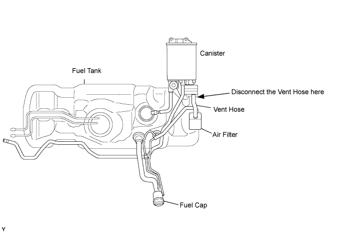
Reinstall the fuel cap.
Disconnect the vent hose.
Connect the EVAP pressure tester tool to the canister with the adapter.
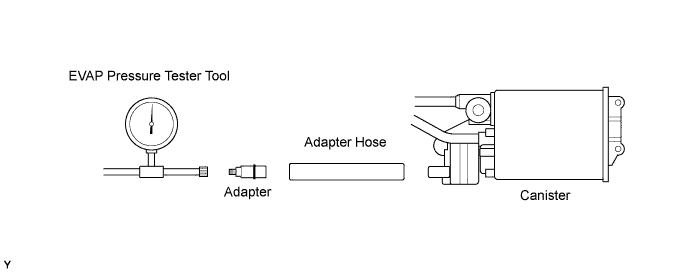
Pressurize the EVAP system to 3.2 to 3.7 kPa (24 to 28 mmHg).
Apply soapy water to the piping and connecting parts of the EVAP system.
Look for areas where bubbles appear. This indicates leak point.
Repair or replace the leak point.
|
| ||||
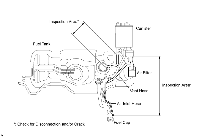
| 30.REPLACE CHARCOAL CANISTER ASSEMBLY |
Replace the canister assembly.
|
| ||||
| 31.REPLACE DUTY VACUUM SWITCHING VALVE (PURGE VSV) |
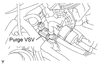 |
Disconnect the connector and the hoses from the purge VSV.
Remove the purge VSV.
Install a new purge VSV.
Reconnect the connector and hoses.
|
| ||||
| 32.REPAIR OR REPLACE HARNESS AND CONNECTOR |
|
| ||||
| 33.REPLACE EVAP HOSE (INTAKE MANIFOLD - PURGE VSV) |
|
| ||||
| 34.INSPECT INTAKE MANIFOLD (EVAP PURGE PORT) |
Check that the EVAP purge port of the intake manifold is not clogged. If necessary, replace the intake manifold.
|
| ||||
| 35.REPLACE ECM |
replace the ECM (Click here).
|
| ||||
| 36.REPAIR OR REPLACE PARTS AND COMPONENTS INDICATED BY OUTPUT DTCS |
Repair the malfunctioning areas indicated by the DTCs that had been confirmed when the vehicle was brought in.
|
| ||||
| 37.PERFORM EVAP SYSTEM CHECK (AUTO OPERATION) |
Clear DTCs (Click here).
On the intelligent tester, select the following menu items: DIAGNOSIS / ENHANCED OBD II / SYSTEM CHECK / EVAP SYS CHECK / AUTO OPERATION.
After the SYSTEM CHECK is completed, check for pending DTCs by selecting the following menu items: DIAGNOSIS / ENHANCED OBD II / DTC INFO / PENDING CODES.
| NEXT | ||
 | ||
| ||
| KEY-OFF MONITOR CONFIRMATION |
Preconditions
The monitor will not run unless:
Monitor Conditions
Monitor Status
| PURGE FLOW MONITOR CONFIRMATION (P0441) |
Preconditions
The monitor will not run unless:
Monitor Conditions
Monitor Status
| MID | TID | Scaling | Description of Test Value | Minimum Test Limit | Maximum Test Limit |
| $3D | $C9 | Multiply by 0.001 [kPa] | Test value for small leak (P0456) Refer to pressure D* | Minimum test limit for small leak | Maximum test limit for small leak |
| $3D | $CA | Multiply by 0.001 [kPa] | Test value for gross leak (P0455) Refer to pressure E* | Minimum test limit for gross leak | Maximum test limit for gross leak |
| $3D | $CB | Multiply by 0.001 [kPa] | Test value for leak detection pump stuck OFF (P2401) Refer to pressure A* | Minimum test limit for leak detection pump stuck OFF | Maximum test limit for leak detection pump stuck OFF |
| $3D | $CD | Multiply by 0.001 [kPa] | Test value for leak detection pump stuck ON (P2402) Refer to pressure A* | Minimum test limit for leak detection pump stuck ON | Maximum test limit for leak detection pump stuck ON |
| $3D | $CE | Multiply by 0.001 [kPa] | Test value for vent valve stuck OFF (vent) (P2420) Refer to pressure C* | Minimum test limit for vent valve stuck ON | Maximum test limit for vent valve stuck ON |
| $3D | $CF | Multiply by 0.001 [kPa] | Test value for vent valve stuck ON (P2419) Refer to pressure A* | Minimum test limit for vent valve stuck OFF | Maximum test limit for vent valve stuck OFF |
| $3D | $D0 | Multiply by 0.001 [kPa] | Test value for reference orifice low flow (P043E) Refer to pressure B* | Minimum test limit for reference orifice low flow | Maximum test limit for reference orifice low flow |
| $3D | $D1 | Multiply by 0.001 [kPa] | Test value for reference orifice high flow (P043F) Refer to pressure A* | Minimum test limit for reference orifice high flow | Maximum test limit for reference orifice high flow |
| $3D | $D4 | Multiply by 0.001 [kPa] | Test value for Purge VSV stuck closed (P0441) Refer to pressure F* | Minimum test limit for Purge VSV stuck closed | Maximum test limit for Purge VSV stuck closed |
| $3D | $D5 | Multiply by 0.001 [kPa] | Test value for Purge VSV stuck open (P0441) Refer to pressure E* | Minimum test limit for Purge VSV stuck open | Maximum test limit for Purge VSV stuck open |
| $3D | $D7 | Multiply by 0.001 [kPa] | Test value for purge flow (P0441) Refer to pressure G* | Minimum test limit for purge flow | Maximum test limit for purge flow |