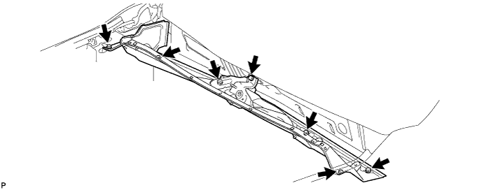
Remove the 7 bolts and front cowl top outer panel.
ENGINE ASSEMBLY > REMOVAL |
| 1. DISCHARGE FUEL SYSTEM PRESSURE |
| 2. PRECAUTION |
| 3. DISCONNECT CABLE FROM NEGATIVE BATTERY TERMINAL |
| 4. REMOVE HOOD SUB-ASSEMBLY |
Remove the 4 bolts, 2 clips and hood.
| 5. REMOVE FRONT WIPER MOTOR AND LINK ASSEMBLY |
| 6. REMOVE FRONT COWL TOP OUTER PANEL SUB-ASSEMBLY |
Disconnect the washer hose.
Remove the 7 bolts and front cowl top outer panel.
| 7. REMOVE NO. 1 ENGINE UNDER COVER |
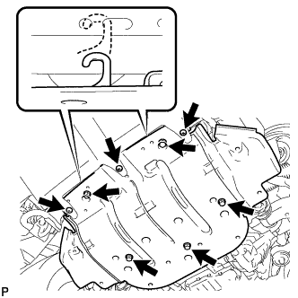 |
Remove the 3 screws and 5 bolts.
Unhook the engine under cover from the vehicle body as shown in the illustration.
| 8. REMOVE FRONT FENDER APRON SEAL LH |
Remove the 6 clips and front fender apron seal.
| 9. REMOVE FRONT FENDER APRON SEAL RH |
Remove the 6 clips and front fender apron seal.
| 10. REMOVE FRONT FENDER APRON SEAL REAR LH |
Remove the 5 clips and fender apron seal.
| 11. REMOVE FRONT FENDER APRON SEAL REAR RH |
Remove the 5 clips and fender apron seal.
| 12. DRAIN ENGINE OIL |
Remove the oil filler cap.
Remove the oil pan drain plug and drain the engine oil into a container.
Install a new gasket and the oil pan drain plug.
| 13. DRAIN ENGINE COOLANT |
Loosen the radiator drain cock plug and 2 cylinder block drain cock plugs.
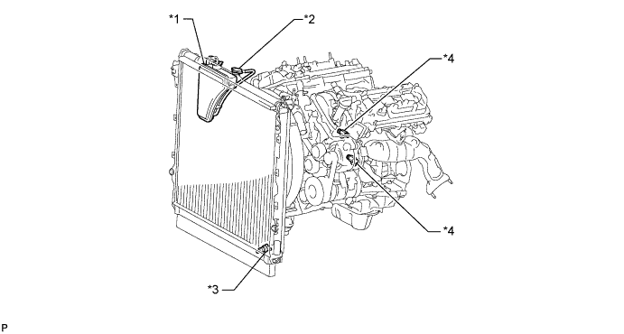
| *1 | Radiator Reservoir | *2 | Radiator Cap |
| *3 | Radiator Drain Cook Plug | *4 | Cylinder Block Drain Cock Plug |
Remove the radiator cap. Then drain the coolant.
Tighten the 2 cylinder block drain cock plugs.
Tighten the radiator drain cock plug by hand.
| 14. REMOVE AIR CLEANER CAP AND HOSE |
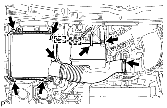 |
Remove the air cleaner cap and hose.
Disconnect the mass air flow meter connector, vacuum hose and ventilation hose and detach the 4 clamps.
Loosen the clamp.
Detach the 4 hook clamps, and then remove the air cleaner cap and hose.
| 15. REMOVE AIR CLEANER CASE SUB-ASSEMBLY |
Remove the air cleaner filter element.
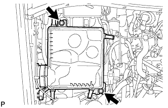 |
Remove the 2 bolts and air cleaner case.
| 16. REMOVE RADIATOR HOSE INLET |
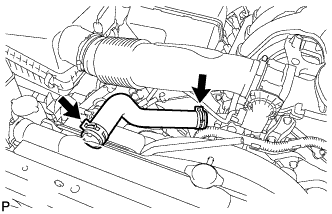 |
| 17. REMOVE RADIATOR HOSE OUTLET |
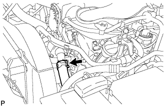 |
Disconnect the radiator hose outlet from the water inlet.
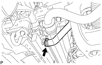 |
Remove the radiator hose outlet.
| 18. REMOVE FAN SHROUD |
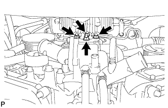 |
Loosen the 4 nuts holding the fluid coupling fan.
Remove the fan and generator V-belt (Click here).
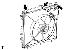 |
Disconnect the reservoir hose from the radiator tank upper.
Remove the 2 bolts holding the fan shroud.
Remove the 4 nuts of the fluid coupling fan, and then remove the shroud together with the coupling fan.
Remove the fan pulley from the water pump.
| 19. REMOVE RADIATOR ASSEMBLY |
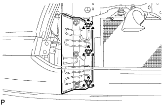 |
Using a clip remover, remove the 3 clips and disconnect the radiator side deflector RH.
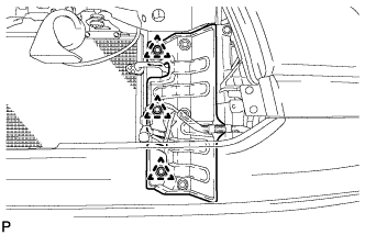 |
Using a clip remover, remove the 3 clips and disconnect the radiator side deflector LH.
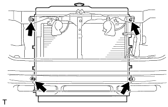 |
Remove the 4 bolts and radiator.
| 20. REMOVE AIR TUBE ASSEMBLY |
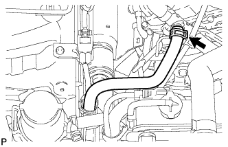 |
Disconnect the air injection system hose from the air tube assembly.
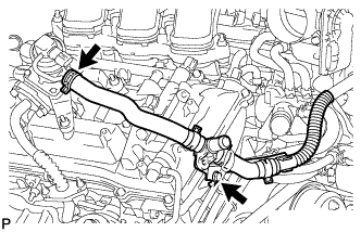 |
for Bank 1 Side:
Remove the bolt and disconnect the air tube assembly from the emission control valve set.
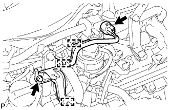 |
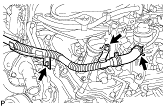
Disconnect the purge VSV connector.
Detach the 3 wire harness clamps from the intake air surge tank and bracket.
Remove the bolt and wire harness clamp bracket.
 |
for Bank 2 Side:
Remove the 2 bolts and disconnect the air tube assembly from the No. 2 emission control valve set.
| 21. REMOVE INTAKE AIR SURGE TANK |
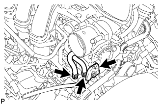 |
Disconnect the throttle body connector.
Disconnect the No. 4 water by-pass hose.
Disconnect the No. 5 water by-pass hose.
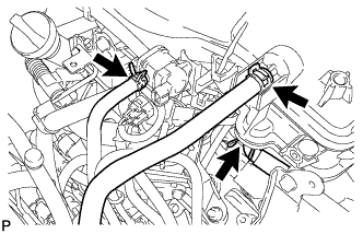 |
Disconnect the No. 1 fuel vapor feed hose.
Disconnect the vacuum hose.
Disconnect the No. 1 ventilation hose.
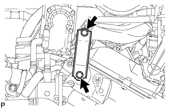 |
Remove the 2 bolts and throttle body bracket.
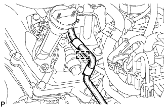 |
Using a clip remover, detach the wire harness clamp.
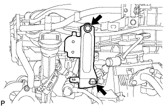 |
Remove the 2 bolts and No. 1 surge tank stay.
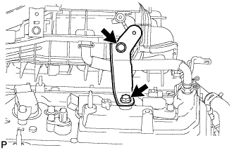 |
Remove the 2 bolts and No. 2 surge tank stay.
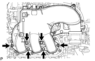 |
Remove the 2 nuts, 4 bolts and intake air surge tank.
Remove the gasket.
| 22. REMOVE FAN AND GENERATOR V BELT |
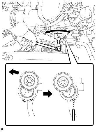 |
While turning the belt tensioner counterclockwise, align the service hole for the belt tensioner and the belt tensioner fixing position, and then insert a bar of 6 mm (0.236 in.) into the service hole to fix the belt tensioner in place.
Remove the V belt.
| 23. DISCONNECT VANE PUMP ASSEMBLY |
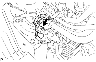 |
Disconnect the connector.
Detach the wire harness clamp.
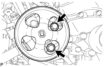 |
Remove the 2 bolts and disconnect the vane pump.
| 24. REMOVE FRONT NO. 3 EXHAUST PIPE SUB-ASSEMBLY (for Regular Cab Standard Deck) |
Remove the 2 bolts and 2 nuts.
Disconnect the exhaust pipe from the exhaust pipe support and remove the 2 gaskets.
| 25. REMOVE FRONT NO. 2 EXHAUST PIPE ASSEMBLY (for Regular Cab Standard Deck) |
Disconnect the air fuel ratio sensor connector.
Disconnect the heated oxygen sensor connector.
Remove the 3 nuts, exhaust pipe and gasket.
| 26. REMOVE FRONT NO. 2 EXHAUST PIPE ASSEMBLY (except Regular Cab Standard Deck) |
Disconnect the air fuel ratio sensor connector.
Disconnect the heated oxygen sensor connector.
Remove the 3 nuts, 2 bolts, exhaust pipe and gasket.
| 27. REMOVE FRONT EXHAUST PIPE ASSEMBLY |
Disconnect the air fuel ratio sensor connector.
Disconnect the heated oxygen sensor connector and detach the 2 clamps.
Remove the 2 bolts.
Remove the 3 nuts, exhaust pipe and 2 gaskets.
| 28. REMOVE MANIFOLD STAY |
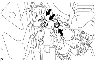 |
Remove the 3 bolts and manifold stay.
| 29. REMOVE AIR TUBE |
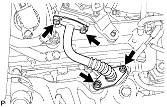 |
Remove the 2 bolts, 2 nuts and air tube.
Remove the 2 gaskets from the air tube.
| 30. REMOVE NO. 1 EXHAUST MANIFOLD HEAT INSULATOR |
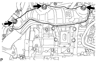 |
Remove the 3 bolts and heat insulator.
| 31. REMOVE EXHAUST MANIFOLD SUB-ASSEMBLY RH |
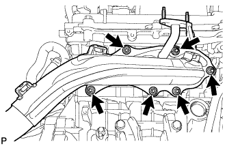 |
Remove the 6 nuts, manifold and gasket.
| 32. REMOVE NO. 2 MANIFOLD STAY |
Disconnect the wire harness connector.
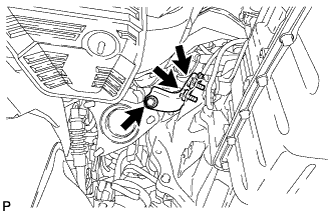 |
Remove the 3 bolts and No. 2 manifold stay.
| 33. REMOVE NO. 2 AIR TUBE |
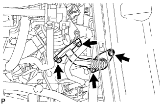 |
Remove the 2 bolts, 2 nuts and No. 2 air tube.
Remove the 2 gaskets from the No. 2 air tube.
| 34. REMOVE NO. 2 EXHAUST MANIFOLD HEAT INSULATOR |
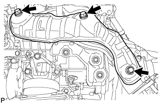 |
Remove the 3 bolts and heat insulator.
| 35. REMOVE EXHAUST MANIFOLD SUB-ASSEMBLY LH |
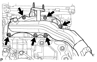 |
Remove the 6 nuts, manifold and gasket.
| 36. REMOVE GENERATOR ASSEMBLY |
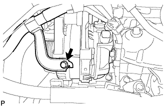 |
Remove the bolt and disconnect the wire harness bracket.
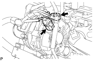 |
Open the terminal cap.
Remove the nut and disconnect the wire harness from terminal B.
Disconnect the generator connector from the generator assembly.
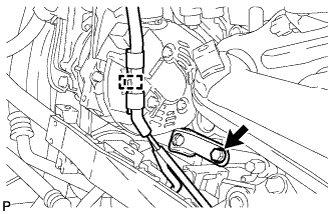 |
Disconnect the wire harness clamp.
Remove the bolt and disconnect the generator bracket.
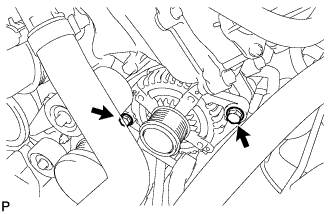 |
Remove the 2 bolts and generator assembly.
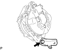 |
Remove the bolt and generator bracket.
| 37. REMOVE STARTER COVER (for 1.4 kW Type) |
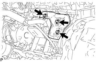 |
Remove the 3 bolts and starter cover.
| 38. REMOVE STARTER ASSEMBLY (for 1.4 kW Type) |
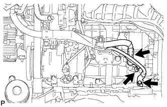 |
Remove the bolt and disconnect the ground wire.
Disconnect the starter connector.
Remove the nut and bolt, and then disconnect the starter wire.
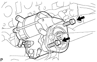 |
Remove the 2 bolts and starter.
| 39. REMOVE STARTER ASSEMBLY (for 1.6 kW Type) |
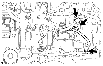 |
Remove the bolt and disconnect the ground wire.
Disconnect the starter connector.
Remove the terminal cap.
Remove the nut and disconnect the starter wire.
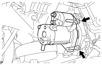 |
Remove the 2 bolts and starter.
| 40. REMOVE DRIVE PLATE AND TORQUE CONVERTER SETTING BOLT |
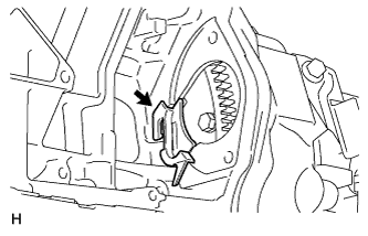 |
Remove the flywheel housing side cover.
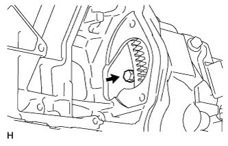 |
Turn the crankshaft to gain access to the 6 bolts and remove each bolt while holding the crankshaft pulley setting bolt with a wrench.
| 41. DISCONNECT ENGINE WIRE |
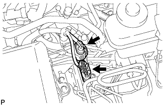 |
Disconnect the 2 air injection control driver connectors.
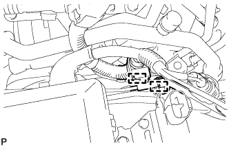 |
Detach the 2 wire harness clamps.
Remove the junction block cover.
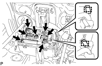 |
Disconnect the 7 connectors, detach the 2 clamps and disconnect the junction block connector from the junction block.
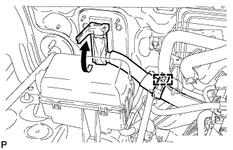 |
Detach the clamp and disconnect the ECM connector (Click here).
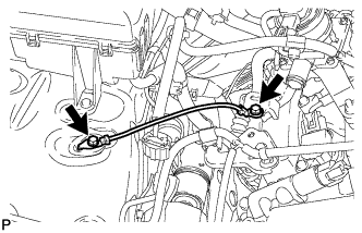 |
Remove the 2 bolts and ground cable.
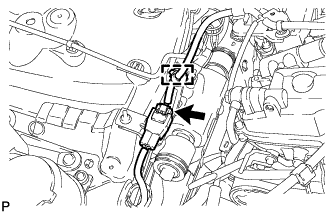 |
Disconnect the air pump connector and detach the clamp.
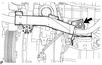 |
Remove the bolt, detach the claw and disconnect the engine wire harness.
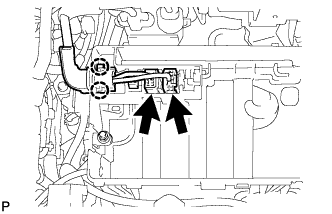 |
Disconnect the 2 connectors, detach the 2 claws and disconnect the engine room junction block connector from the engine room junction block.
| 42. DISCONNECT COOLER COMPRESSOR ASSEMBLY |
Disconnect the cooler compressor connector.
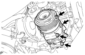 |
Remove the 2 bolts, 2 nuts and 2 stud bolts and disconnect the cooler compressor.
| 43. DISCONNECT HEATER WATER HOSE ASSEMBLY |
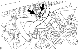 |
Disconnect the heater water inlet and outlet hoses.
| 44. DISCONNECT NO. 1 AND NO. 2 FUEL PIPES |
Remove the No. 2 fuel pipe clamp from the fuel tube connector.
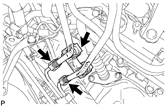 |
Disconnect the No. 1 and No. 2 fuel pipes (Click here).
| 45. REMOVE PROPELLER SHAFT ASSEMBLY |
| 46. REMOVE AUTOMATIC TRANSMISSION ASSEMBLY |
| 47. REMOVE REAR NO. 1 ENGINE MOUNTING INSULATOR |
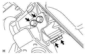 |
Remove the 4 bolts and rear engine mounting insulator from the transmission.
| 48. REMOVE DRIVE PLATE AND RING GEAR SUB-ASSEMBLY |
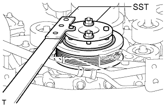 |
Using SST, hold the crankshaft.
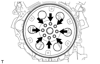 |
Remove the 8 bolts, rear spacer, drive plate and front spacer.
| 49. REMOVE ENGINE ASSEMBLY |
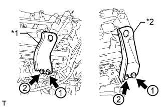 |
Install 2 engine hangers with 4 bolts as shown in the illustration.
| *1 | No. 1 Engine Hanger |
| *2 | No. 2 Engine Hanger |
| No. 1 Engine Hanger | 12281-31110 |
| No. 2 Engine Hanger | 12282-31140 |
| Bolt | 91671-C0830 |
Attach an engine sling device and hang the engine with a chain block.
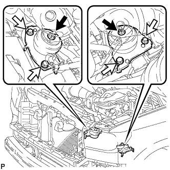 |
Remove the 2 nuts, 4 bolts and front engine mounting insulator LH and RH.
Lift the engine out of the vehicle carefully.
 | Nut |
 | Bolt |
| 50. INSTALL ENGINE TO ENGINE STAND |
Install the engine to an engine stand with bolts.
Remove the 2 engine hangers and 4 bolts.
| 51. REMOVE FRONT NO. 2 ENGINE MOUNTING BRACKET LH |
Remove the bolt and front No. 2 engine mounting bracket LH.