1UR-FE ENGINE MECHANICAL ENGINE UNIT INSTALLATION
PROCEDURE

 86011A
1.INSTALL NOISE FILTER
RH Side:
Install the noise filter to the cylinder head cover with the bolt.
- Torque:
- 10 N*m (102 kgf*cm, 7 ft.*lbf)
LH Side:
Install the noise filter to the cylinder head cover with the bolt.
- Torque:
- 10 N*m (102 kgf*cm, 7 ft.*lbf)
19500
2.INSTALL IGNITION COIL ASSEMBLY
Install the 8 ignition coils with the 8 bolts.
- Torque:
- 10 N*m (102 kgf*cm, 7 ft.*lbf)
89615
3.INSTALL KNOCK SENSOR
16294
4.INSTALL NO. 11 WATER BY-PASS HOSE
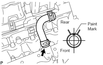
Install the No. 11 water by-pass hose.
- HINT:
-
The direction of the hose clamp is indicated in the illustration.
82121
5.INSTALL ENGINE WIRE
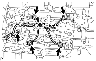
Connect the 3 clamps and 4 knock sensor connectors to install the engine wire.
12611
6.INSTALL NO. 1 ENGINE COVER
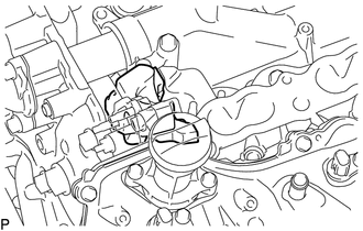
Install the No. 1 engine cover.
11212
7.INSTALL NO. 2 ENGINE COVER
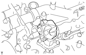
Install the No. 2 engine cover.
12215
8.INSTALL SEPARATOR CASE
16603
9.INSTALL NO. 1 IDLER PULLEY SUB-ASSEMBLY
16173
10.INSTALL WATER PUMP PULLEY
16355
11.INSTALL FRONT WATER BY-PASS JOINT
16323
12.INSTALL WATER INLET HOUSING
16206
13.INSTALL WATER BY-PASS PIPE SUB-ASSEMBLY
14.INSTALL AIR TUBE SUB-ASSEMBLY RH
16261G
15.INSTALL NO. 1 WATER BY-PASS HOSE
12613
16.INSTALL NO. 3 ENGINE COVER
12614
17.INSTALL NO. 4 ENGINE COVER
83530
18.INSTALL OIL PRESSURE SENDER GAUGE ASSEMBLY
23807
19.INSTALL FUEL DELIVERY PIPE SUB-ASSEMBLY RH
23808
20.INSTALL FUEL DELIVERY PIPE SUB-ASSEMBLY LH
12315
21.INSTALL FRONT NO. 1 ENGINE MOUNTING BRACKET LH
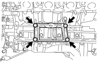
Install the mounting bracket with the 4 bolts.
- Torque:
- 35 N*m (357 kgf*cm, 26 ft.*lbf)
12311
22.INSTALL FRONT NO. 1 ENGINE MOUNTING BRACKET RH
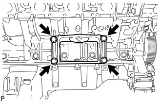
Install the mounting bracket with the 4 bolts.
- Torque:
- 35 N*m (357 kgf*cm, 26 ft.*lbf)
12361
23.INSTALL FRONT ENGINE MOUNTING INSULATOR RH
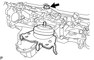
Install the mounting insulator with the nut.
- Torque:
- 72 N*m (734 kgf*cm, 53 ft.*lbf)
12362A
24.INSTALL FRONT ENGINE MOUNTING INSULATOR LH
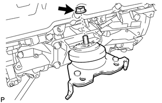
Install the mounting insulator with the nut.
- Torque:
- 72 N*m (734 kgf*cm, 53 ft.*lbf)
11415A
25.INSTALL CYLINDER BLOCK WATER DRAIN COCK SUB-ASSEMBLY
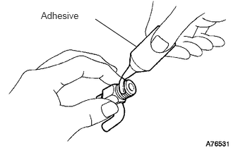
Apply adhesive to 2 or 3 threads of the drain cocks.
- Adhesive:
Toyota Genuine Adhesive 1344, Three Bond 1344 or equivalent
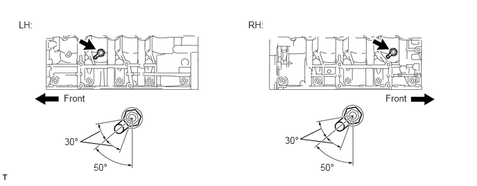
Install the water drain cocks.
- Torque:
- 30 N*m (306 kgf*cm, 22 ft.*lbf)
Tighten the drain cocks up to an additional 360° so that the drain cock pipes are within the range shown in the illustration.
- NOTICE:
- ·
Do not rotate the drain cocks more than 1 revolution (360°) after tightening the drain cocks to the specified torque.
·Do not loosen the drain cocks to adjust them. If an adjustment is necessary, remove the drain cocks and reinstall them.
Install the water drain cock plugs to the water drain cocks.
- Torque:
- 13 N*m (130 kgf*cm, 9 ft.*lbf)
25680
26.INSTALL EGR COOLER ASSEMBLY
16294
27.CONNECT NO. 11 WATER BY-PASS HOSE
16296
28.INSTALL NO. 8 WATER BY-PASS HOSE
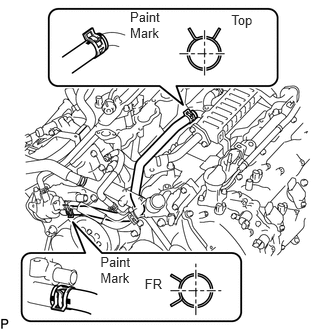
Install the No. 8 water by-pass hose.
- HINT:
-
The direction of the hose clamp is indicated in the illustration.
29.INSTALL NO. 3 WATER BY-PASS PIPE SUB-ASSEMBLY
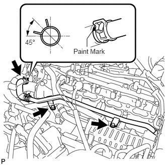
Install the No. 3 water by-pass pipe with the 2 bolts and connect the hose.
- HINT:
-
The direction of the hose clamp is indicated in the illustration.
- Torque:
- 10 N*m (102 kgf*cm, 7 ft.*lbf)
17363Q
30.INSTALL NO. 3 AIR TUBE
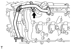
Install the No. 3 air tube with the bolt.
- Torque:
- 10 N*m (102 kgf*cm, 7 ft.*lbf)
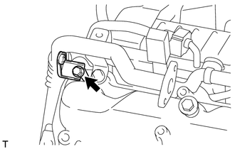
Install the wire harness clamp bracket with the bolt.
- Torque:
- 8.0 N*m (82 kgf*cm, 71 in.*lbf)
17364A
31.INSTALL NO. 4 AIR TUBE
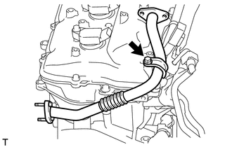
Install the No. 4 air tube with the bolt.
- Torque:
- 10 N*m (102 kgf*cm, 7 ft.*lbf)
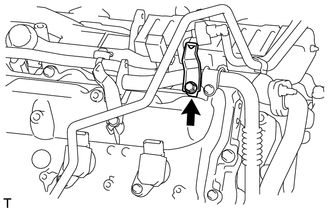
Install the wire harness clamp bracket with the bolt.
- Torque:
- 8.0 N*m (82 kgf*cm, 71 in.*lbf)
25710
32.INSTALL AIR SWITCHING VALVE ASSEMBLY (for Bank 2)
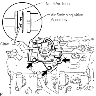
Install a new gasket and the air switching valve assembly with the 3 bolts.
- Torque:
- 24 N*m (245 kgf*cm, 18 ft.*lbf)
- NOTICE:
-
Make sure the gasket's claws are not caught between the air switching valve assembly and No. 3 air tube.
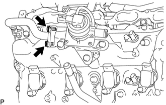
Install the 2 bolts.
- Torque:
- 10 N*m (102 kgf*cm, 7 ft.*lbf)
25710
33.INSTALL AIR SWITCHING VALVE ASSEMBLY (for Bank 1)
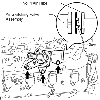
Install a new gasket and the air switching valve assembly with the 3 bolts.
- Torque:
- 24 N*m (245 kgf*cm, 18 ft.*lbf)
- NOTICE:
-
Make sure the gasket's claws are not caught between the air switching valve assembly and No. 4 air tube.
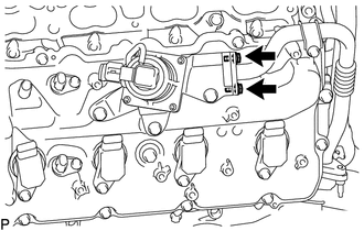
Install the 2 bolts.
- Torque:
- 10 N*m (102 kgf*cm, 7 ft.*lbf)
23902
34.INSTALL NO. 2 FUEL TUBE SUB-ASSEMBLY
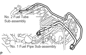
Install the No. 2 fuel tube (See page Engine / Hybrid System>1UR-FE FUEL>FUEL SYSTEM>PRECAUTION).
23801P
35.INSTALL NO. 1 FUEL PIPE SUB-ASSEMBLY
Install the No. 1 fuel pipe (See page Engine / Hybrid System>1UR-FE FUEL>FUEL SYSTEM>PRECAUTION).
36.INSTALL ENGINE WIRE
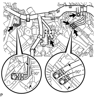
Engine Rear Side:
Install the 4 bolts.
- Torque:
- 8.4 N*m (86 kgf*cm, 74 in.*lbf)
Connect the clamp and connector.
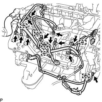
Engine RH Side:
Connect the 6 clamps.
Connect the oil pressure sender gauge connector.
Connect the air switching valve connector.
Connect the noise filter connector.
Connect the fuel injector connector.
Connect the 2 VVT sensor connectors.
Connect the 4 ignition coil connectors.
Connect the 2 camshaft timing control valve connectors.
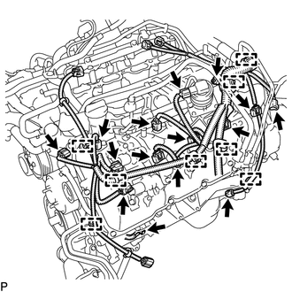
Engine LH Side:
Connect the 8 clamps and install the engine wire with the bolt.
- Torque:
- 20 N*m (204 kgf*cm, 15 ft.*lbf)
Connect the noise filter connector.
Connect the fuel injector connector.
Connect the engine coolant temperature sensor connector.
Connect the air switching valve connector.
Connect the crankshaft position sensor connector.
Connect the camshaft position sensor connector.
Connect the 2 VVT sensor connectors.
Connect the 4 ignition coil connectors.
Connect the 2 camshaft timing control valve connectors.