WF1AM TRANSFER TOUCH SELECT 2-4 AND HIGH-LOW SYSTEM P17A7 Transfer Synchronization Actuator Circuit High
DESCRIPTION
This DTC is detected when a short to B+ is detected in the solenoid coil drive circuit.
| DTC Code | DTC Detection Condition
1.
Diagnosis Condition 2.
Malfunction Status 3.
Malfunction Time 4.
Other |
Trouble Area |
|---|---|---|
| P17A7 | 1.
Ignition switch ON (when not switching between 2WD and 4H) 2.
Short to B+ in the solenoid coil drive circuit 3.
1 second or more 4.
1 trip detection logic |
·
Wire harness and connector ·
4 wheel drive control ECU ·
Solenoid coil sub-assembly ·
Transfer shift actuator assembly |
WIRING DIAGRAM
Refer to DTCs P17A5 and P17A6 (See page Drivetrain>WF1AM TRANSFER>TOUCH SELECT 2-4 AND HIGH-LOW SYSTEM>P17A5).
PROCEDURE
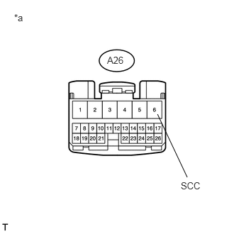
Disconnect the 4 wheel drive control ECU connector.
Measure the voltage according to the value(s) in the table below.
- Standard Voltage:
Tester Connection Switch Condition Specified Condition A26-6 (SCC) - Body ground Ignition switch ON Below 1 V
| *a | Front view of wire harness connector
(to 4 Wheel Drive Control ECU) |
OK
NG
Disconnect the A26 4 wheel drive control ECU connector.
Disconnect the D67 transfer shift actuator assembly connector.
Measure the voltage according to the value(s) in the table below.
- Standard Voltage:
Tester Connection Switch Condition Specified Condition A26-6 (SCC) or D67-3 (SCC) - Body ground Ignition switch ON Below 1 V
OK
NG
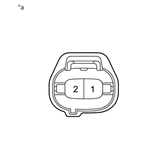
Disconnect the A solenoid coil sub-assembly connector.
Measure the voltage according to the value(s) in the table below.
- Standard Voltage:
Tester Connection Switch Condition Specified Condition 2 - Body ground Ignition switch ON Below 1 V
| *a | Component without harness connected
(Solenoid Coil Sub-assembly) |
OK
NG