STEERING COLUMN STEERING COLUMN ASSEMBLY INSTALLATION
CAUTION / NOTICE / HINT
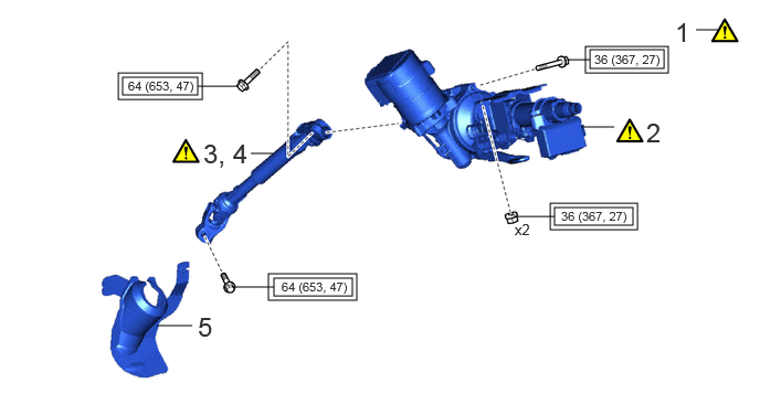
| Procedure | Part Name Code | 
|

|

|
|
|---|---|---|---|---|---|
| 1 | ALIGN FRONT WHEELS FACING STRAIGHT AHEAD | - | ( ) |
- | - |
| 2 | STEERING COLUMN ASSEMBLY | - | ()
|
- | - |
| 3 | INSTALL NO. 2 STEERING INTERMEDIATE SHAFT ASSEMBLY | 45260 | ()
|
- | - |
| 4 | CONNECT NO. 2 STEERING INTERMEDIATE SHAFT ASSEMBLY | 45260 | ()
|
- | - |
| 5 | COLUMN HOLE COVER SILENCER SHEET | 45259A | - | - | - |

|
Tightening torque for "Major areas involving basic vehicle performance such as moving/turning/stopping": N*m (kgf*cm, ft.*lbf) | - | - |
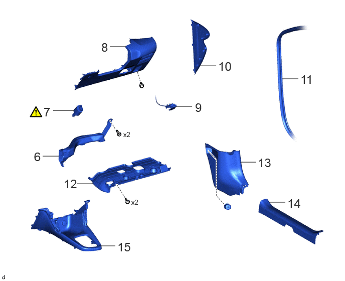
| Procedure | Part Name Code |
|
|
|
|
|---|---|---|---|---|---|
| 6 | NO. 1 AIR DUCT | 87211 | - | - | - |
| 7 | STOP LIGHT SWITCH ASSEMBLY | 84340 | ()
|
- | - |
| 8 | LOWER INSTRUMENT PANEL FINISH PANEL ASSEMBLY | 55480D | - | - | - |
| 9 | HOOD LOCK CONTROL LEVER SUB-ASSEMBLY | 53601 | - | - | - |
| 10 | NO. 1 INSTRUMENT SIDE PANEL | 55317E | - | - | - |
| 11 | FRONT DOOR OPENING TRIM WEATHERSTRIP RH | 62311B | - | - | - |
| 12 | NO. 1 INSTRUMENT PANEL UNDER COVER SUB-ASSEMBLY | 55606 | - | - | - |
| 13 | COWL SIDE TRIM BOARD RH | 62111C | - | - | - |
| 14 | FRONT DOOR SCUFF PLATE RH | 67913B | - | - | - |
| 15 | FRONT CONSOLE BOX SUB-ASSEMBLY | 58810J | - | - | - |
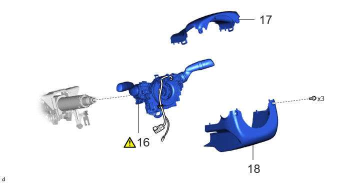
| Procedure | Part Name Code |
|
|
|
|
|---|---|---|---|---|---|
| 16 | TURN SIGNAL SWITCH ASSEMBLY WITH SPIRAL CABLE SUB-ASSEMBLY | - | ()
|
- | - |
| 17 | UPPER STEERING COLUMN COVER | 45286B | - | - | - |
| 18 | LOWER STEERING COLUMN COVER | 45287 | - | - | - |
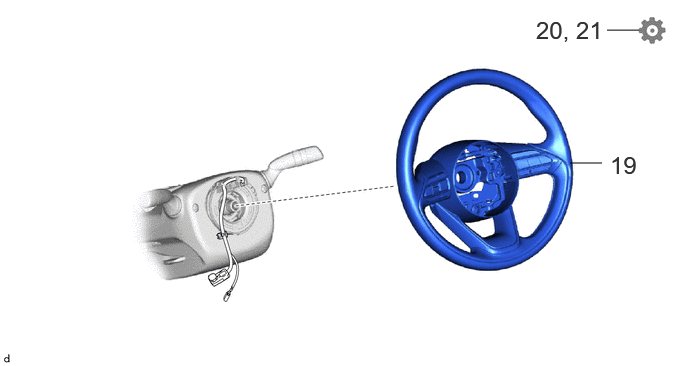
| Procedure | Part Name Code |
|
|
|
|
|---|---|---|---|---|---|
| 19 | STEERING WHEEL ASSEMBLY | 45100 | - | - | - |
| 20 | PERFORM POWER STEERING ECU INITIAL SETTING | - | - | - | ()
|
| 21 | PERFORM CALIBRATION | - | - | - | ()
|
PROCEDURE

 1.ALIGN FRONT WHEELS FACING STRAIGHT AHEAD
2.INSTALL STEERING COLUMN ASSEMBLY
|
|
|
- Torque:
- 36 N*m (367 kgf*cm, 27 ft.*lbf)
45260
3.INSTALL NO. 2 STEERING INTERMEDIATE SHAFT ASSEMBLY
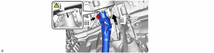
| *a | Matchmark | - | - |

|
Install in this direction | - | - |
Align the matchmarks on the No. 2 steering intermediate shaft assembly and steering column assembly.
Install the No. 2 steering intermediate shaft assembly to the steering column assembly.
Install the bolt.
- Torque:
- 64 N*m (653 kgf*cm, 47 ft.*lbf)
45260
4.CONNECT NO. 2 STEERING INTERMEDIATE SHAFT ASSEMBLY
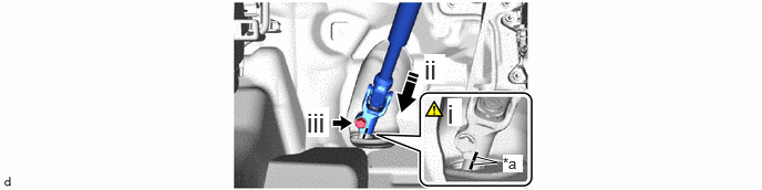
| *a | Matchmark | - | - |
|
|
Connect in this direction | - | - |
Align the matchmarks on the No. 2 steering intermediate shaft assembly and steering gear assembly.
Connect the No. 2 steering intermediate shaft assembly to the steering gear assembly.
Install the bolt.
- Torque:
- 64 N*m (653 kgf*cm, 47 ft.*lbf)
45259A
5.INSTALL COLUMN HOLE COVER SILENCER SHEET
87211
6.INSTALL NO. 1 AIR DUCT
84340
7.INSTALL STOP LIGHT SWITCH ASSEMBLY
55480D
8.INSTALL LOWER INSTRUMENT PANEL FINISH PANEL ASSEMBLY
53601
9.CONNECT HOOD LOCK CONTROL LEVER SUB-ASSEMBLY
55317E
10.INSTALL NO. 1 INSTRUMENT SIDE PANEL
62311B
11.INSTALL FRONT DOOR OPENING TRIM WEATHERSTRIP RH
55606
12.INSTALL NO. 1 INSTRUMENT PANEL UNDER COVER SUB-ASSEMBLY
62111C
13.INSTALL COWL SIDE TRIM BOARD RH
67913B
14.INSTALL FRONT DOOR SCUFF PLATE RH
58810J
15.INSTALL FRONT CONSOLE BOX SUB-ASSEMBLY
16.INSTALL TURN SIGNAL SWITCH ASSEMBLY WITH SPIRAL CABLE SUB-ASSEMBLY
|
|
|
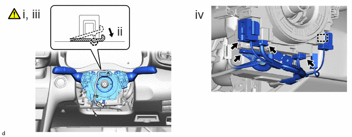
Using pliers, expand the clamp.
While holding the clamp expanded, install the turn signal switch assembly with spiral cable sub-assembly to the steering column assembly and engage the claw.
Return the clamp to its original position.
Connect the 4 connectors and engage the clamp to the turn signal switch assembly with spiral cable sub-assembly.
45286B
17.INSTALL UPPER STEERING COLUMN COVER
45287
18.INSTALL LOWER STEERING COLUMN COVER
45100
19.INSTALL STEERING WHEEL ASSEMBLY
20. PERFORM POWER STEERING ECU INITIAL SETTING
21.PERFORM CALIBRATION