M15A-FKS ENGINE MECHANICAL ENGINE UNIT INSTALLATION
CAUTION / NOTICE / HINT
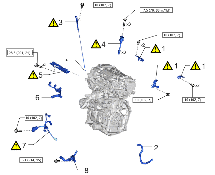
| Procedure | Part Name Code | 
|

|

|
|
|---|---|---|---|---|---|
| 1 | WIRE HARNESS CLAMP BRACKET | - | ( ) |
- | - |
| 2 | NO. 4 WATER BY-PASS HOSE | 16281 | - | - | - |
| 3 | ENGINE OIL LEVEL DIPSTICK GUIDE | 11452D | ()
|
- | - |
| 4 | IGNITION COIL ASSEMBLY | 19500 | ()
|
- | - |
| 5 | FUEL DELIVERY PIPE | 23814B | ()
|
- | - |
| 6 | NO. 6 ENGINE WIRE | 82126A | - | - | - |
| 7 | SENSOR WIRE | 82219C | ()
|
- | - |
| 8 | WATER BY-PASS PIPE ASSEMBLY | - | - | - | - |

|
Tightening torque for "Major areas involving basic vehicle performance such as moving/turning/stopping" : N*m (kgf*cm, ft.*lbf) | 
|
N*m (kgf*cm, ft.*lbf): Specified torque |
| ● | Non-reusable part | - | - |
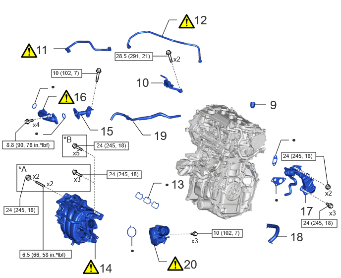
| Procedure | Part Name Code |
|
|
|
|
|---|---|---|---|---|---|
| 9 | FUEL PUMP LIFTER ASSEMBLY | 23470 | - | - | - |
| 10 | NO. 2 FUEL PIPE SUB-ASSEMBLY | 23802B | - | - | - |
| 11 | NO. 2 FUEL TUBE SUB-ASSEMBLY | 23902 | ()
|
- | - |
| 12 | FUEL TUBE SUB-ASSEMBLY | 23901 | ()
|
- | - |
| 13 | NO. 1 INTAKE MANIFOLD TO HEAD GASKET | 17177 | - | - | - |
| 14 | INTAKE MANIFOLD | 17111 | ()
|
- | - |
| 15 | EGR VALVE ADAPTER | 25624 | - | - | - |
| 16 | NO. 1 EGR PIPE SUB-ASSEMBLY | 25601 | ()
|
- | - |
| 17 | EGR COOLER ASSEMBLY | 25680 | - | - | - |
| 18 | NO. 2 VENTILATION HOSE | 12262 | - | - | - |
| 19 | FUEL VAPOR FEED HOSE ASSEMBLY | 23820 | - | - | - |
| 20 | THROTTLE BODY WITH MOTOR ASSEMBLY | 22030 | ()
|
- | - |
| *A | w/ Stud Bolt | *B | w/o Stud Bolt |
|
|
N*m (kgf*cm, ft.*lbf): Specified torque | ● | Non-reusable part |
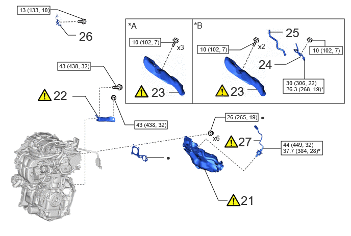
| Procedure | Part Name Code |
|
|
|
|
|---|---|---|---|---|---|
| 21 | EXHAUST MANIFOLD | 17141 | ()
|
- | - |
| 22 | MANIFOLD STAY | 17118 | ()
|
- | - |
| 23 | NO. 1 EXHAUST MANIFOLD HEAT INSULATOR | 17167 | ()
|
- | - |
| 24 | NO. 1 VACUUM PIPE | 25733A | - | - | - |
| 25 | VACUUM TRANSMITTING HOSE ASSEMBLY | 25760 | - | - | - |
| 26 | WIRE HARNESS CLAMP BRACKET | - | - | - | - |
| 27 | AIR FUEL RATIO SENSOR | 89467B | ()
|
- | - |
| *A | w/o Differential Pressure Sensor | *B | w/ Differential Pressure Sensor |
|
|
N*m (kgf*cm, ft.*lbf): Specified torque | ● | Non-reusable part |
| * | For use with SST | - | - |
CAUTION / NOTICE / HINT
- NOTICE:
-
This procedure includes the installation of small-head bolts. Refer to Small-Head Bolts of Basic Repair Hint to identify the small-head bolts.
-
Click hereGeneral>INTRODUCTION>REPAIR INSTRUCTION>PRECAUTION
PROCEDURE

 1.INSTALL WIRE HARNESS CLAMP BRACKET
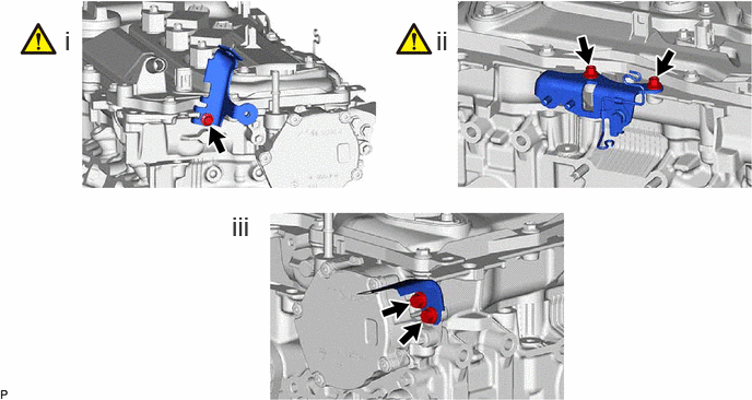
Using an 8 mm socket wrench, install the wire harness clamp bracket to the camshaft housing sub-assembly with the bolt.
- Torque:
- 10 N*m (102 kgf*cm, 7 ft.*lbf)
Install the wire harness clamp bracket to the camshaft housing sub-assembly with the 2 bolts.
- Torque:
- 10 N*m (102 kgf*cm, 7 ft.*lbf)
Using an 8 mm socket wrench, install the wire harness clamp bracket to the camshaft housing sub-assembly with the 2 bolts.
- Torque:
- 10 N*m (102 kgf*cm, 7 ft.*lbf)
16281
2.INSTALL NO. 4 WATER BY-PASS HOSE
11452D
3.INSTALL ENGINE OIL LEVEL DIPSTICK GUIDE
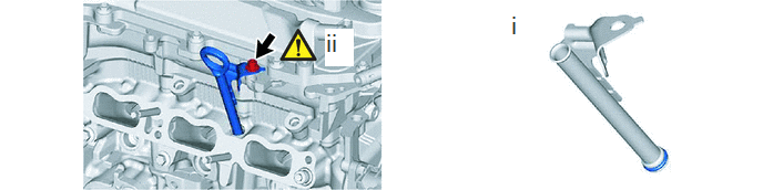
Install the new O-ring to the engine oil level dipstick guide.
- HINT:
-
Apply a light coat of engine oil to a new O-ring.
Using an 8 mm socket wrench, install the engine oil level dipstick guide to the cylinder head sub-assembly with the bolt.
- Torque:
- 10 N*m (102 kgf*cm, 7 ft.*lbf)
19500
4.INSTALL IGNITION COIL ASSEMBLY
|
|
Click here()
|
23814B
5.INSTALL FUEL DELIVERY PIPE
|
|
Click here()
|
82126A
6.INSTALL NO. 6 ENGINE WIRE
82219C
7.INSTALL SENSOR WIRE
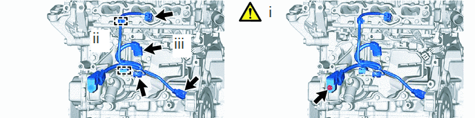
Install the sensor wire to the water inlet with thermostat sub-assembly with the bolt.
- Torque:
- 10 N*m (102 kgf*cm, 7 ft.*lbf)
Engage the 2 clamps.
Connect the 4 connectors.
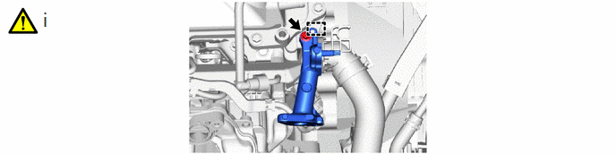
8.INSTALL WATER BY-PASS PIPE ASSEMBLY
- Torque:
- 21 N*m (214 kgf*cm, 15 ft.*lbf)
23470
9.INSTALL FUEL PUMP LIFTER ASSEMBLY
23802B
10.INSTALL NO. 2 FUEL PIPE SUB-ASSEMBLY
- Torque:
- 28.5 N*m (291 kgf*cm, 21 ft.*lbf)
23902
11.INSTALL NO. 2 FUEL TUBE SUB-ASSEMBLY
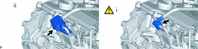
Connect the No. 2 fuel tube sub-assembly to the No. 2 fuel pipe sub-assembly.
Click hereEngine / Hybrid System>M15A-FKS (FUEL)>FUEL SYSTEM>PRECAUTION
Install the fuel pipe clamp to the fuel tube connector.
23901
12.INSTALL FUEL TUBE SUB-ASSEMBLY
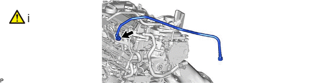
Connect the fuel tube sub-assembly to the No. 2 fuel pipe sub-assembly.
Click hereEngine / Hybrid System>M15A-FKS (FUEL)>FUEL SYSTEM>PRECAUTION
17177
13.INSTALL NO. 1 INTAKE MANIFOLD TO HEAD GASKET
17111
14.INSTALL INTAKE MANIFOLD
|
|
Click here()
|
25624
15.INSTALL EGR VALVE ADAPTER
Using an 8 mm socket wrench, install the EGR valve adapter with the bolt.
- Torque:
- 10 N*m (102 kgf*cm, 7 ft.*lbf)
25601
16.INSTALL NO. 1 EGR PIPE SUB-ASSEMBLY
|
|
Click here()
|
25680
17.INSTALL EGR COOLER ASSEMBLY
12262
18.INSTALL NO. 2 VENTILATION HOSE
23820
19.INSTALL FUEL VAPOR FEED HOSE ASSEMBLY
22030
20.INSTALL THROTTLE BODY WITH MOTOR ASSEMBLY
17141
21.INSTALL EXHAUST MANIFOLD
|
|
Click here()
|
17118
22.INSTALL MANIFOLD STAY
|
|
Click here()
|
17167
23.INSTALL NO. 1 EXHAUST MANIFOLD HEAT INSULATOR
|
|
Click here()
|
25733A
24.INSTALL NO. 1 VACUUM PIPE (w/ Differential Pressure Sensor)
|
|
Click here()
|
25760
25.CONNECT VACUUM TRANSMITTING HOSE ASSEMBLY (w/ Differential Pressure Sensor)
26.INSTALL WIRE HARNESS CLAMP BRACKET
89467B
27.INSTALL AIR FUEL RATIO SENSOR
|
|
Click here()
|