U340E AUTOMATIC TRANSMISSION / TRANSAXLE AUTOMATIC TRANSAXLE ASSEMBLY REMOVAL
PROCEDURE

 1.DRAIN AUTOMATIC TRANSAXLE FLUID
28800
2.REMOVE BATTERY
74431
3.REMOVE BATTERY TRAY
74411
4.REMOVE BATTERY CARRIER (for LHD)
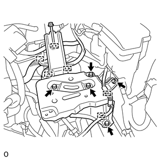
Disengage the 6 wire harness clamps and separate the wire harness from the battery carrier.
Remove the 5 bolts and the battery carrier.
74411
5.REMOVE BATTERY CARRIER (for RHD)
17700
6.REMOVE AIR CLEANER ASSEMBLY
17771A
7.REMOVE AIR CLEANER BRACKET
28100
8.REMOVE STARTER ASSEMBLY
33820B
9.SEPARATE TRANSMISSION CONTROL CABLE ASSEMBLY
10.SEPARATE WIRE HARNESS
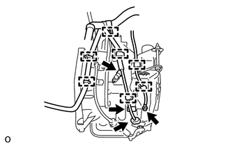
Remove the bolt and separate the No. 3 engine wire from the automatic transaxle assembly.
Disconnect the park/neutral position switch connector.
Disconnect the transmission wire connector.
Disconnect the transmission revolution sensor connector.
Disengage the 7 clamps and separate the wire harness.
32921D
11.DISCONNECT INLET OIL COOLER HOSE
32922A
12.DISCONNECT OUTLET OIL COOLER HOSE
13.REMOVE FRONT DRIVE SHAFT ASSEMBLIES
51201
14.REMOVE FRONT SUSPENSION CROSSMEMBER SUB-ASSEMBLY
15.SUPPORT ENGINE ASSEMBLY
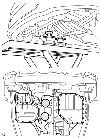
Place the wooden blocks or plate lift attachments in the positions shown in the illustration and set an engine lifter underneath the engine assembly.

|
Attachment Placement Positions |
- NOTICE:
- ·
Place the wooden blocks or plate lift attachments so that the engine assembly with transaxle is level.
·As the engine assembly with transaxle is very heavy, be sure to support it securely.
·To prevent deformation of the oil pan, never set any attachments against the oil pan of the engine assembly.
11361J
16.REMOVE FLYWHEEL HOUSING UNDER COVER
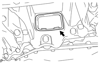
Remove the flywheel housing under cover.
32101A
17.REMOVE TORQUE CONVERTER SETTING BOLT
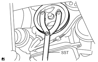
Use SST to hold the crankshaft pulley in place.
- SST
- 09960-10010 (09962-01000, 09963-01000)
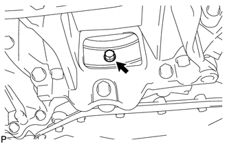
Remove the 6 torque converter setting bolts.
12313
18.REMOVE ENGINE MOVING CONTROL ROD BRACKET
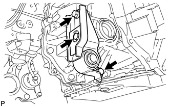
Remove the 3 bolts and the engine moving control rod bracket.
12325A
19.REMOVE ENGINE MOUNTING BRACKET LH
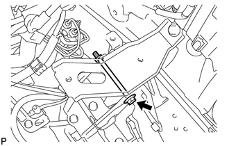
Remove the bolt and nut, and separate the engine mounting insulator LH from the engine mounting bracket LH.
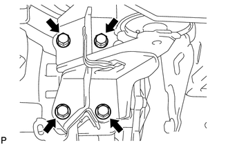
Remove the 4 bolts and the engine mounting bracket LH from the automatic transaxle assembly.
30500
20.REMOVE AUTOMATIC TRANSAXLE ASSEMBLY
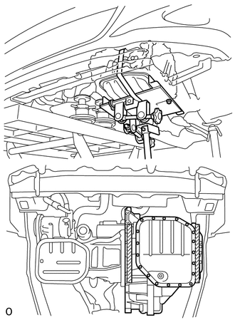
On a flat location, set the attachment in the positions shown in the illustration, and set the automatic transaxle assembly.
|
|
Attachment Placement Positions |
- NOTICE:
-
To prevent deformation of the oil pan, never set any attachments against the oil pan of the automatic transaxle assembly.
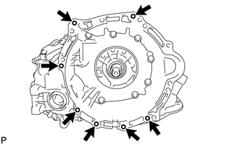
Remove the 7 bolts and the automatic transaxle assembly from the engine assembly.
- NOTICE:
-
To prevent damage to the knock pins, do not pry between the transaxle and engine.
32000
21.REMOVE TORQUE CONVERTER ASSEMBLY
Remove the torque converter assembly from the automatic transaxle assembly.
- NOTICE:
-
Remove the torque converter assembly from the input shaft horizontally.
33403M
22.REMOVE SPEEDOMETER DRIVEN HOLE COVER SUB-ASSEMBLY
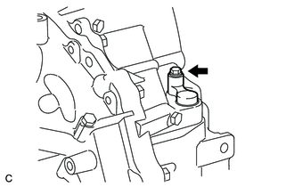
Remove the bolt and the speedometer driven hole cover sub-assembly from the automatic transaxle assembly.
Remove the O-ring from the speedometer driven hole cover.
33823
23.REMOVE NO. 1 TRANSMISSION CONTROL CABLE BRACKET
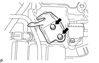
Remove the 2 bolts and the No. 1 transmission control cable bracket from the automatic transaxle assembly.
32921
24.DISCONNECT INLET NO. 1 OIL COOLER TUBE
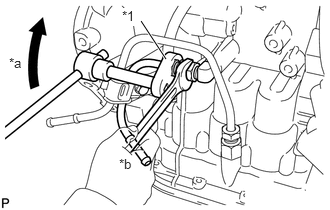
Using a union nut wrench 14 mm, disconnect the inlet No. 1 oil cooler tube while holding the oil cooler tube union with a wrench.
| *1 | Union Nut Wrench 14 mm |
| *a | Turn |
| *b | Hold |
32922
25.DISCONNECT OUTLET NO. 1 OIL COOLER TUBE
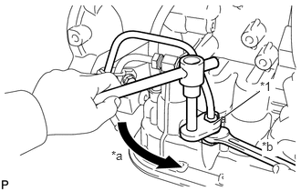
Using a union nut wrench 14 mm, disconnect the outlet No. 1 oil cooler tube while holding the oil cooler tube union with a wrench.
| *1 | Union Nut Wrench 14 mm |
| *a | Turn |
| *b | Hold |
26.REMOVE NO. 2 OIL COOLER TUBE CLAMP
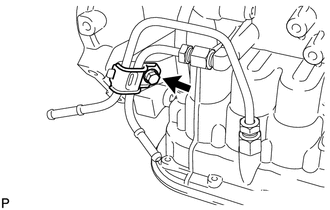
Remove the bolt and the No. 2 oil cooler tube clamp from the transmission oil filler tube sub-assembly.
Remove the inlet No. 1 oil cooler tube and the outlet No. 1 oil cooler tube from the automatic transaxle assembly.
35103
27.REMOVE TRANSMISSION OIL LEVEL DIPSTICK SUB-ASSEMBLY
Remove the transmission oil level dipstick sub-assembly from the transmission oil filler tube sub-assembly.
35013
28.REMOVE TRANSMISSION OIL FILLER TUBE SUB-ASSEMBLY
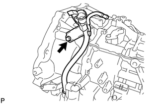
Disconnect the breather hose from the transmission oil filler tube sub-assembly.
Remove the bolt and the transmission oil filler tube sub-assembly from the automatic transaxle assembly.
Remove the O-ring from the transmission oil filler tube sub-assembly.
29.REMOVE WIRE HARNESS CLAMP BRACKET
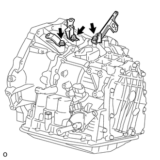
Remove the 3 bolts and the 3 wire harness clamp brackets from the automatic transaxle assembly.