U441E AUTOMATIC TRANSMISSION / TRANSAXLE AUTOMATIC TRANSAXLE ASSEMBLY INSTALLATION
PROCEDURE

 1.INSTALL WIRE HARNESS CLAMP BRACKET
Install the 3 wire harness clamp brackets with the 3 bolts.
- Torque:
- 13 N*m (130 kgf*cm, 9 ft.*lbf)
35013
2.INSTALL TRANSMISSION OIL FILLER TUBE SUB-ASSEMBLY
Apply Toyota Genuine ATF Type T-IV to a new O-ring, and install it to the transmission oil filler tube sub-assembly.
Install the transmission oil filler tube sub-assembly to the automatic transaxle assembly with the bolt.
- Torque:
- 5.5 N*m (56 kgf*cm, 49 in.*lbf)
Connect the breather hose to the transmission oil filler tube sub-assembly.
35103
3.INSTALL TRANSMISSION OIL LEVEL DIPSTICK SUB-ASSEMBLY
Install the transmission oil level dipstick sub-assembly into the transmission oil filler tube sub-assembly.
4.INSTALL NO. 1 OIL COOLER TUBE CLAMP
Temporarily install the outlet No. 1 oil cooler tube to the oil cooler tube union.
Temporarily install the inlet No. 1 oil cooler tube to the oil cooler tube union.
Install the No. 1 oil cooler tube clamp to the transmission oil filler tube sub-assembly with the bolt.
- Torque:
- 5.5 N*m (56 kgf*cm, 49 in.*lbf)
32922
5.CONNECT OUTLET NO. 1 OIL COOLER TUBE
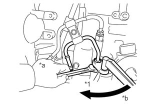
Using a union nut wrench 14 mm, connect the outlet No. 1 oil cooler tube while holding the oil cooler tube union with a wrench.
| *1 | Union Nut Wrench 14 mm |
| *a | Hold |
| *b | Turn |
- Torque:
- 34 N*m (347 kgf*cm, 25 ft.*lbf)
- NOTICE:
-
Use the formula to calculate special torque values for situations where the union nut wrench is combined with a torque wrench (See page General>INTRODUCTION>REPAIR INSTRUCTION>PRECAUTION).
32921
6.CONNECT INLET NO. 1 OIL COOLER TUBE
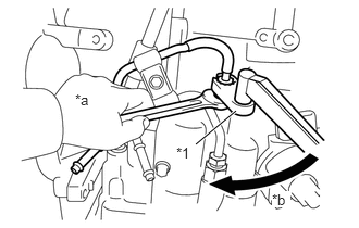
Using a union nut wrench 14 mm, connect the inlet No. 1 oil cooler tube while holding the oil cooler tube union with a wrench.
| *1 | Union Nut Wrench 14 mm |
| *a | Hold |
| *b | Turn |
- Torque:
- 34 N*m (347 kgf*cm, 25 ft.*lbf)
- NOTICE:
-
Use the formula to calculate special torque values for situations where the union nut wrench is combined with a torque wrench (See page General>INTRODUCTION>REPAIR INSTRUCTION>PRECAUTION).
33823
7.INSTALL NO. 1 TRANSMISSION CONTROL CABLE BRACKET
Install the No. 1 transmission control cable bracket to the automatic transaxle assembly with the 2 bolts.
- Torque:
- 12 N*m (122 kgf*cm, 9 ft.*lbf)
33403M
8.INSTALL SPEEDOMETER DRIVEN HOLE COVER SUB-ASSEMBLY (w/ ABS)
Apply Toyota Genuine ATF Type T-IV to a new O-ring, and install it to the speedometer driven hole cover.
Install the speedometer driven hole cover sub-assembly to the automatic transaxle assembly.
- Torque:
- 11 N*m (115 kgf*cm, 8 ft.*lbf)
83181G
9.INSTALL SPEEDOMETER SENSOR (w/o ABS)
10.INSPECT TORQUE CONVERTER ASSEMBLY
11.INSTALL TORQUE CONVERTER ASSEMBLY
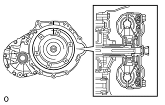
Engage the splines of the input shaft and turbine runner.
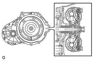
Engage the splines of the stator shaft and the stator while turning the torque converter assembly.
- HINT:
-
If the stator shaft splines are difficult to engage with the stator splines, move the torque converter back approximately 10 mm (0.394 in.) and engage the splines while rotating the torque converter assembly.
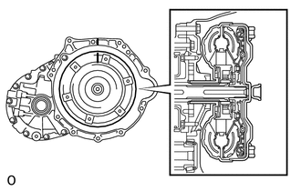
Turn the torque converter assembly to insert the key of the oil pump drive gear into the groove of the torque converter assembly.
Clean the torque converter setting bolt holes.
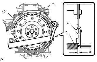
Using a vernier caliper and a straightedge, measure dimension A between the transaxle contact surface of the engine and the torque converter contact surface of the drive plate.
| *1 | Engine Surface |
| *2 | Drive Plate Surface |
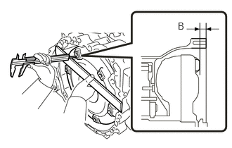
Using a vernier caliper and straightedge, measure dimension B shown in the illustration and check that dimension B is more than dimension A, which was measured in the previous step.
- Standard:
B = A + 1 mm (0.0394 in.) or more
- NOTICE:
- ·
Make sure to deduct the thickness of the straightedge.
·If the transaxle is installed to the engine with the torque converter not sufficiently inserted, the torque converter may be damaged.
·Do not include the thickness of the set block.
30500
12.INSTALL AUTOMATIC TRANSAXLE ASSEMBLY
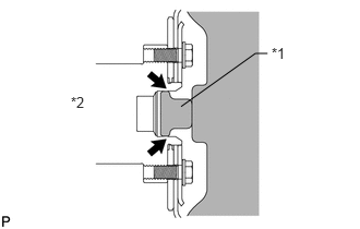
Apply clutch spline grease to the round of the crankshaft contact surface with the torque converter centerpiece.
| *1 | Torque Converter Centerpiece |
| *2 | Crankshaft |

|
Clutch spline grease |
- Grease:
Toyota Genuine Clutch Spline Grease or equivalent
- Maximum spread:
Approximately 1 g (0.0353 oz.)
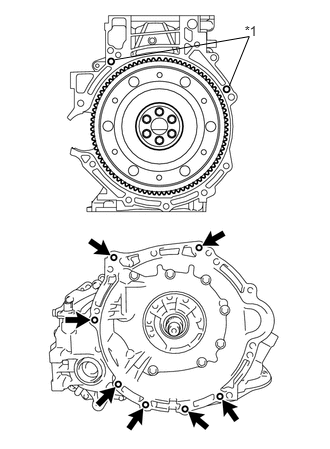
Confirm that 2 knock pins are on the transaxle contact surface of the engine cylinder block before transaxle installation.
| *1 | Knock Pin |
Keeping the engine assembly and the automatic transaxle assembly in a horizontal position, align the knock pins with each hole on the automatic transaxle assembly and tighten the 7 bolts.
- Torque:
- 30 N*m (301 kgf*cm, 22 ft.*lbf)
- NOTICE:
- ·
Confirm that the 2 knock pins are installed to the transaxle contact surface of the engine cylinder block before installing the transaxle.
·Do not forcibly pry on the automatic transaxle assembly.
·Check that the torque converter assembly rotates.
12325A
13.INSTALL ENGINE MOUNTING BRACKET LH
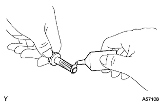
Clean and degrease the bolt and the bolt installation hole.
Apply adhesive to 2 or 3 threads on the end of the 4 bolts.
- Adhesive:
Toyota Genuine Adhesive 1324, Three Bond 1324 or equivalent
Install the engine mounting bracket LH to the automatic transaxle assembly with the 4 bolts.
- Torque:
- 64 N*m (653 kgf*cm, 47 ft.*lbf)
Install the engine mounting insulator LH to the engine mounting bracket LH with the bolt and nut.
- Torque:
- 52 N*m (530 kgf*cm, 38 ft.*lbf)
- NOTICE:
-
Turn the bolt while holding the nut.
12313
14.INSTALL ENGINE MOVING CONTROL ROD BRACKET
Install the engine moving control rod bracket to the automatic transaxle assembly with the 3 bolts.
- Torque:
- 45 N*m (459 kgf*cm, 33 ft.*lbf)
32101G
15.INSTALL TORQUE CONVERTER SETTING BOLT
Remove any adhesive remaining in the 6 torque converter setting bolts.
Apply adhesive to 2 or 3 threads on the end of the 6 torque converter setting bolts.
- Adhesive:
Toyota Genuine Adhesive 1324, Three Bond 1324 or equivalent
Use SST to hold the crankshaft pulley in place.
- SST
- 09960-10010 (09962-01000, 09963-01000)
Install the 6 torque converter setting bolts.
- Torque:
- 28 N*m (286 kgf*cm, 21 ft.*lbf)
- HINT:
-
First install the black-colored bolt, and then the remaining 5 silver-colored bolts.
11361J
16.INSTALL FLYWHEEL HOUSING UNDER COVER
Install the flywheel housing under cover.
51201
17.INSTALL FRONT SUSPENSION CROSSMEMBER SUB-ASSEMBLY
18.INSTALL FRONT DRIVE SHAFT ASSEMBLIES
19.CONNECT OUTLET OIL COOLER HOSE
20.CONNECT INLET OIL COOLER HOSE
21.CONNECT WIRE HARNESS (w/ ABS)
Engage the 8 clamps and install the wire harness.
Connect the transmission revolution sensor connector.
Connect the transmission wire connector.
Connect the park/neutral position switch connector.
Install the No. 3 engine wire to the automatic transaxle assembly with the bolt.
- Torque:
- 26 N*m (260 kgf*cm, 19 ft.*lbf)
22.CONNECT WIRE HARNESS (w/o ABS)
Engage the 9 clamps and install the wire harness.
Connect the speedometer sensor connector.
Connect the transmission revolution sensor connector.
Connect the transmission wire connector.
Connect the park/neutral position switch connector.
Install the No. 3 engine wire to the automatic transaxle assembly with the bolt.
- Torque:
- 26 N*m (260 kgf*cm, 19 ft.*lbf)
33820B
23.INSTALL TRANSMISSION CONTROL CABLE ASSEMBLY
28100
24.INSTALL STARTER ASSEMBLY
17771A
25.INSTALL AIR CLEANER BRACKET
17700
26.INSTALL AIR CLEANER ASSEMBLY
74411
27.INSTALL BATTERY CARRIER
74431
28.INSTALL BATTERY TRAY
28800
29.INSTALL BATTERY
30.ADD AUTOMATIC TRANSAXLE FLUID
31.INSPECT AUTOMATIC TRANSAXLE FLUID
32.INSPECT FOR AUTOMATIC TRANSAXLE FLUID LEAK
33.ADJUST SHIFT LEVER POSITION
34.INSPECT SHIFT LEVER POSITION
35. RESET MEMORY (AT initialization)
Perform Reset Memory (AT initialization) when replacing the automatic transaxle assembly (See page Drivetrain>U441E (AUTOMATIC TRANSMISSION / TRANSAXLE)>AUTOMATIC TRANSAXLE SYSTEM>INITIALIZATION).