HEATING / AIR CONDITIONING AIR CONDITIONING UNIT REMOVAL
CAUTION / NOTICE / HINT
- CAUTION:
-
Some of these service operations affect the SRS airbag system. Read the precautionary notices concerning the SRS airbag system before servicing (See page Vehicle Interior>SUPPLEMENTAL RESTRAINT SYSTEMS>AIRBAG SYSTEM (w/ VSC/Built-in Type Yaw Rate Sensor)>PRECAUTION).
PROCEDURE

 1. PRECAUTION
- NOTICE:
-
After turning the ignition switch off, waiting time may be required before disconnecting the cable from the battery terminal. Therefore, make sure to read the disconnecting the cable from the battery terminal notice before proceeding with work (See page General>INTRODUCTION>REPAIR INSTRUCTION>PRECAUTION).
2.RECOVER REFRIGERANT FROM REFRIGERATION SYSTEM
3.DRAIN ENGINE COOLANT (for 1NZ-FE)
4.DRAIN ENGINE COOLANT (for 2NZ-FE)
5.DISCONNECT CABLE FROM NEGATIVE BATTERY TERMINAL
- CAUTION:
-
Wait at least 90 seconds after disconnecting the cable from the negative (-) battery terminal to disable the SRS system.
- NOTICE:
-
When disconnecting the cable, some systems need to be initialized after the cable is reconnected.
-
Click hereGeneral>INTRODUCTION>REPAIR INSTRUCTION>INITIALIZATION
6.REMOVE WINDSHIELD WIPER MOTOR AND LINK
55815E
7.REMOVE FRONT NO. 1 VENTILATOR SEAL
55735D
8.REMOVE FRONT AIR SHUTTER SEAL RH
55722C
9.REMOVE COWL TOP TO COWL INNER BRACE
55711
10.REMOVE COWL TOP OUTER PANEL
88707B
11.DISCONNECT SUCTION TUBE SUB-ASSEMBLY B
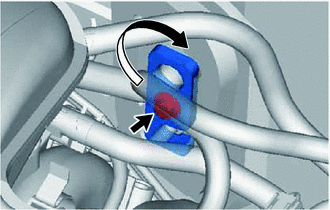
Remove the bolt.
Turn the hook connector clockwise and disconnect the suction tube.
Remove the O-ring from the suction tube.
- NOTICE:
-
Seal the openings of the disconnected parts using vinyl tape to prevent the entry of moisture and foreign matter.
88706A
12.DISCONNECT LIQUID TUBE SUB-ASSEMBLY A
Disconnect the liquid tube.
Remove the O-ring from the liquid tube.
- NOTICE:
-
Seal the opening of the disconnected parts using vinyl tape to prevent the entry of moisture and foreign matter.
87246A
13.DISCONNECT HEATER WATER OUTLET HOSE A
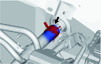
Slide the clip and disconnect the heater water outlet hose from the air conditioning unit.
87245A
14.DISCONNECT HEATER WATER INLET HOSE A
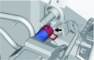
Slide the clip and disconnect the heater water inlet hose from the air conditioning unit.
55303B
15.REMOVE LOWER INSTRUMENT PANEL SUB-ASSEMBLY
4520A
16.REMOVE STEERING COLUMN ASSEMBLY (for LHD)
4520A
17.REMOVE STEERING COLUMN ASSEMBLY (for RHD)
55870B
18.REMOVE HEATER TO REGISTER DUCT ASSEMBLY
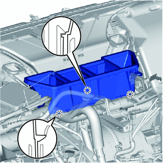
Disengage the 3 claws and remove the heater to register duct.
55950G
19.REMOVE DEFROSTER NOZZLE ASSEMBLY
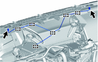
Disconnect the connectors and disengage the clamps, then disconnect the wire harness.
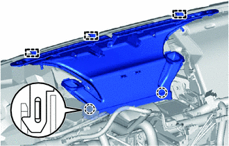
Disengage the 2 claws and 3 guides and remove the defroster nozzle.
88539J
20.SEPARATE DRAIN COOLER HOSE
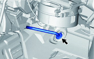
Separate the drain cooler hose.
55306A
21.REMOVE NO. 1 INSTRUMENT PANEL BRACE SUB-ASSEMBLY
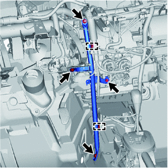
Disengage the 2 clamps.
Remove the 2 bolts, nut and screw, then remove the instrument panel brace.
- HINT:
-
If the vehicle is equipped with knee airbag, remove the knee airbag bracket mounting bolt.
82730
22.REMOVE INSTRUMENT PANEL JUNCTION BLOCK ASSEMBLY
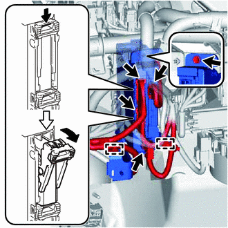
Disengage the clamps.
Disconnect the connectors on the front side.
Remove the bolt and separate the instrument panel junction block.
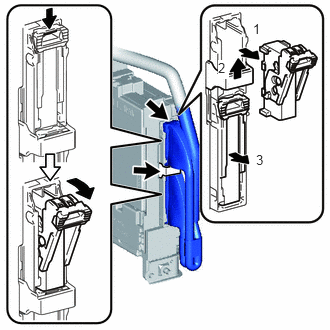
Disconnect the back side connectors and remove the instrument panel junction block as shown in the illustration.
82141
23.SEPARATE INSTRUMENT PANEL WIRE (for LHD)
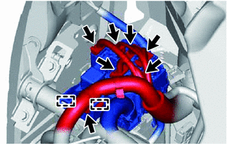
Disconnect the connectors.
Remove the screw.
Disengage the 2 clamps and separate the connector holder.
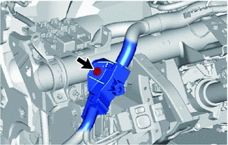
Remove the screw and the wire harness protector.
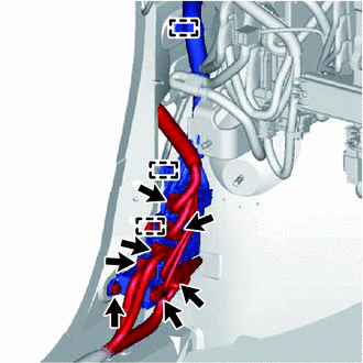
Disconnect the connectors.
Remove the bolt.
Disengage the 3 clamps and remove the connector holder.
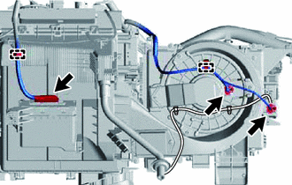
for Automatic Air Conditioning System:
Disconnect the 3 connectors.
Disengage the 2 clamps and disconnect the instrument panel wire.
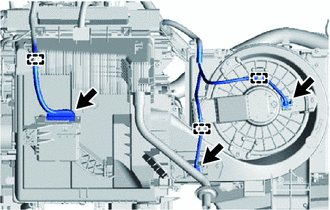
for Manual Air Conditioning System:
Disconnect the 3 connectors.
Disengage the 3 clamps and disconnect the instrument panel wire.
Remove the bolts and disconnect the ground wire.
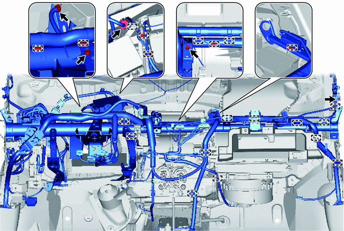
Disconnect the connectors and clamps, then disconnect the instrument panel wire.
82141
24.SEPARATE INSTRUMENT PANEL WIRE (for RHD)
Disconnect the connectors.
Remove the screw.
Disengage the 2 clamps and separate the connector holder.
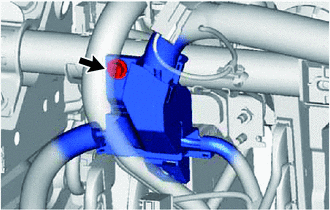
Remove the screw and the wire harness protector.
Disconnect the connectors.
Remove the bolt.
Disengage the 3 clamps and remove the connector holder.
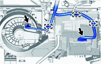
for Automatic Air Conditioning System:
Disconnect the 2 connectors.
Disengage the 3 clamps and disconnect the instrument panel wire.
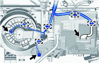
for Manual Air Conditioning System:
Disconnect the 3 connectors.
Disengage the 5 clamps and disconnect the instrument panel wire.
Remove the bolts and disconnect the ground wire.
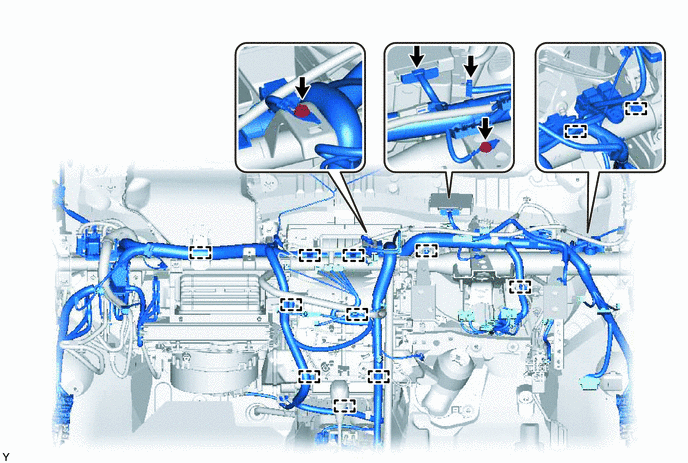
Disconnect the connectors and clamps, then disconnect the instrument panel wire.
55331
25.REMOVE INSTRUMENT PANEL REINFORCEMENT
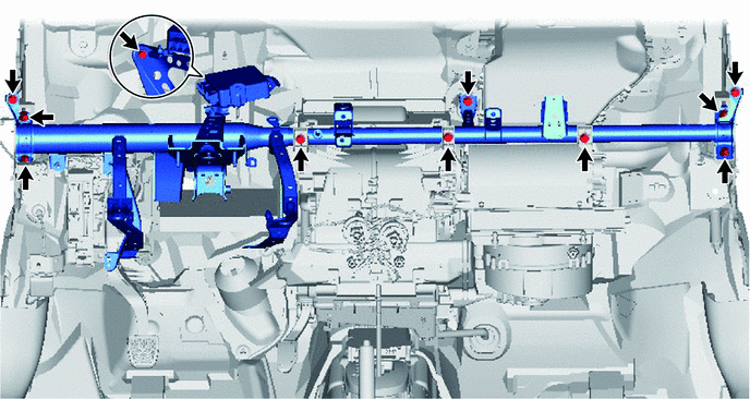
Remove the 8 bolts and 3 screws, then remove the instrument panel reinforcement.
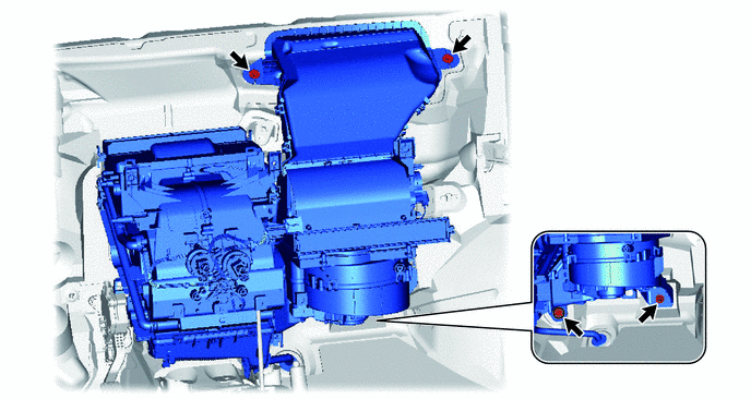
26.REMOVE AIR CONDITIONER UNIT ASSEMBLY
Remove the 3 bolts and nut, then remove the air conditioner unit.
82210K
27.REMOVE AIR CONDITIONING HARNESS ASSEMBLY (for LHD)
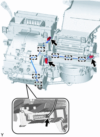
Disconnect the connectors and disengage the clamps, then remove the air conditioning harness.
82210K
28.REMOVE AIR CONDITIONING HARNESS ASSEMBLY (for RHD)
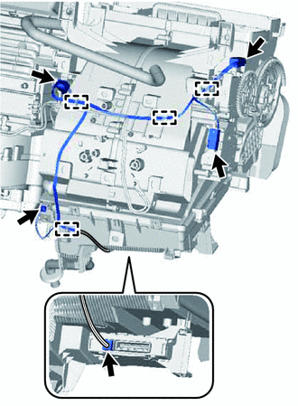
Disconnect the connectors and disengage the clamps, then remove the air conditioning harness.
88650N
29.REMOVE AIR CONDITIONING AMPLIFIER ASSEMBLY (for Automatic Air Conditioning System)
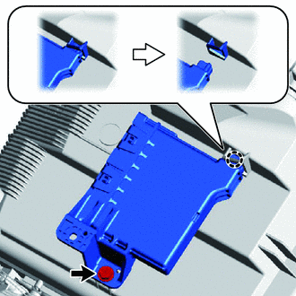
Disconnect the connector.
Remove the screw.
Disengage the claw and remove the air conditioning amplifier as shown in the illustration.
88650N
30.REMOVE AIR CONDITIONING AMPLIFIER ASSEMBLY (for Manual Air Conditioning System)
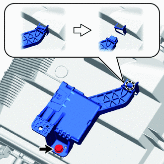
Remove the screw.
Disengage the claw and remove the air conditioning amplifier as shown in the illustration.
87050
31.REMOVE AIR CONDITIONING RADIATOR ASSEMBLY
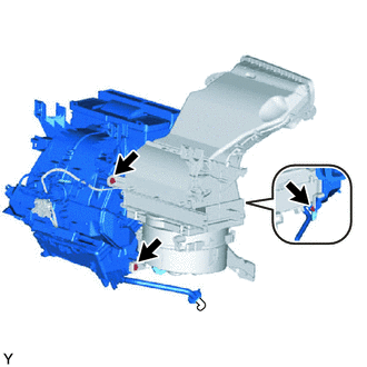
Remove the 3 screws and the air conditioning radiator.
88669B
32.REMOVE COOLER AIR HOSE (for Automatic Air Conditioning System)
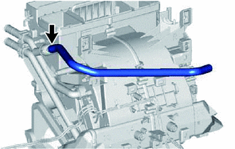
Remove the cooler air hose.
87211
33.REMOVE NO. 1 AIR DUCT
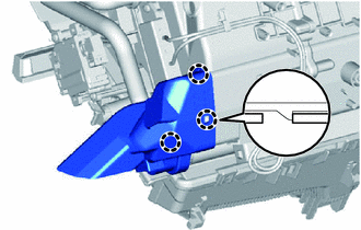
Disengage the 3 claws and remove the air duct.
87211A
34.REMOVE NO. 2 AIR DUCT
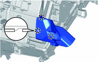
Disengage the 3 claws and remove the air duct.