PRE-CRASH SAFETY PRE-CRASH SAFETY SYSTEM Pre-crash Safety System Circuit
WIRING DIAGRAM
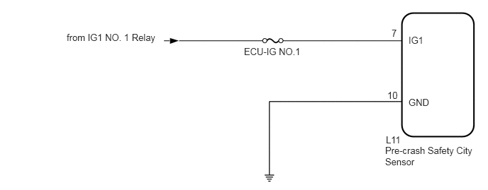
CAUTION / NOTICE / HINT
- NOTICE:
- ·
Inspect the fuses for circuits related to this system before performing the following procedure.
·When replacing the pre-crash safety city sensor, replace it with a new one. If an ECU which was installed to another vehicle is used, the information stored in the pre-crash safety city sensor will not match the information from the vehicle and, as a result, a DTC may be output.
·If the pre-crash safety city sensor has been replaced, or the windshield glass has been replaced or removed/installed, be sure to perform Recognition Camera/Target Position Memory and Recognition Camera Axis Adjust.
·Perform adjustment using "ONE TIME RECOGNITION" or "SEQUENTIAL RECOGNITION".
·ONE TIME RECOGNITION
Click hereVehicle Interior>PRE-CRASH SAFETY>FRONT SENSOR>ADJUSTMENT (ONE TIME RECOGNITION)
·SEQUENTIAL RECOGNITION
Click hereVehicle Interior>PRE-CRASH SAFETY>FRONT SENSOR>ADJUSTMENT (SEQUENTIAL RECOGNITION)
PROCEDURE
Check the customer problem analysis and symptom (See page Vehicle Interior>PRE-CRASH SAFETY>PRE-CRASH SAFETY SYSTEM>HOW TO PROCEED WITH TROUBLESHOOTING).
NEXT
Measure the battery voltage.
- Standard voltage:
11 to 14 V
Using the parts location and system diagram, check the system for blown-out fuses, open or short circuits in the wire harness(es) and connectors that are not properly connected by performing a visual check.
- HINT:
-
If the voltage is 11 V or less, replace or recharge the battery before proceeding to the next step.
NEXT
Check pre-crash safety city sensor.
- NOTICE:
-
DTCs may be output when connectors are disconnected during inspection. Therefore, make sure to clear the DTCs using the GTS once the inspection has been completed.
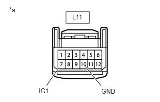
| *a | Front view of wire harness connector
(to Pre-crash safety City Sensor) |
Disconnect the pre-crash safety city sensor connector.
Measure the voltage according to the value(s) in the table below.
- Standard Voltage:
Tester Connection Switch Condition Specified Condition L11-7 (IG1) - Body ground Ignition switch ON 11 to 14 V L11-7 (IG1) - Body ground Ignition switch off Below 1 V
Measure the resistance according to the value(s) in the table below.
- Standard Resistance:
Tester Connection Condition Specified Condition L11-10 (GND) - Body ground Always Below 1 Ω
OK
NG
Use the GTS to check if the CAN communication system is functioning normally (See page Power Source / Network>NETWORKING>CAN COMMUNICATION SYSTEM(w/ Toyota Safety Sense)>DIAGNOSIS SYSTEM).
| Result | Proceed to |
|---|---|
| CAN communication system DTCs are not output | A |
| CAN communication system DTCs are output | B |
A
B
Check for DTCs and note any codes that are output (See page Vehicle Interior>PRE-CRASH SAFETY>PRE-CRASH SAFETY SYSTEM>DTC CHECK / CLEAR).
Clear the DTCs (See page Vehicle Interior>PRE-CRASH SAFETY>PRE-CRASH SAFETY SYSTEM>DTC CHECK / CLEAR).
Recheck for DTCs. Try to reproduce the DTCs by duplicating the conditions indicated by the DTCs. (See page General>INTRODUCTION>HOW TO TROUBLESHOOT ECU CONTROLLED SYSTEMS>HOW TO PROCEED WITH TROUBLESHOOTING).
| Result | Proceed to |
|---|---|
| DTCs are not output | A |
| DTCs are output | B |
A
B
Connect the GTS to the DLC3.
Turn the ignition switch to ON.
Turn the GTS on.
Enter the following menus: Body Electrical / Combination Meter / Trouble Codes.
Check for DTCs (See page Vehicle Interior>PRE-CRASH SAFETY>PRE-CRASH SAFETY SYSTEM>DTC CHECK / CLEAR).
| Result | Proceed to |
|---|---|
| Past DTC U023A is output | A |
| Present DTC U023A is output | B |
A
B
Read the Data List according to the display on the GTS (See page Vehicle Interior>PRE-CRASH SAFETY>PRE-CRASH SAFETY SYSTEM>DATA LIST / ACTIVE TEST).
| Tester Display | Measurement Item/Range | Normal Condition | Diagnostic Note |
|---|---|---|---|
| Low Temperature Status | Displays whether there is a low temperature malfunction / ON or OFF | ON: Pre-crash safety city sensor low temperature malfunction exists
OFF: Pre-crash safety city sensor low temperature malfunction does not exist |
- |
| High Temperature Status | Displays whether there is a high temperature malfunction / ON or OFF | ON: Pre-crash safety city sensor high temperature malfunction exists
OFF: Pre-crash safety city sensor high temperature malfunction does not exist |
- |
| Result | Proceed to |
|---|---|
| Temperature malfunction exists | A |
| Temperature malfunction does not exist | B |
A
B
Return the temperature of the pre-crash safety city sensor to normal.
NEXT
Check for DTCs and note any codes that are output (See page Vehicle Interior>PRE-CRASH SAFETY>PRE-CRASH SAFETY SYSTEM>DTC CHECK / CLEAR).
Clear the DTCs (See page Vehicle Interior>PRE-CRASH SAFETY>PRE-CRASH SAFETY SYSTEM>DTC CHECK / CLEAR).
Recheck for DTCs. Try to reproduce the DTCs by duplicating the conditions indicated by the DTCs (See page General>INTRODUCTION>HOW TO TROUBLESHOOT ECU CONTROLLED SYSTEMS>HOW TO PROCEED WITH TROUBLESHOOTING).
| Result | Proceed to |
|---|---|
| Present DTC is output | A |
| Past DTC is output | B |
A
B
Using the GTS, check the Data List (See page Vehicle Interior>PRE-CRASH SAFETY>PRE-CRASH SAFETY SYSTEM>DATA LIST / ACTIVE TEST).
Using the GTS, perform the Active Test (See page Vehicle Interior>PRE-CRASH SAFETY>PRE-CRASH SAFETY SYSTEM>DATA LIST / ACTIVE TEST).
NEXT